Through January I did some extra work for some extra cash (for extra parts for the Jag). As a result, I spent very little time in the garage. It has been very cold in North Carolina this winter, and January wasn’t the best time to do much of anything without a good heater. The garage space heater just can’t keep up when it gets cold.
I did work on a database of pictures and notes for this site, and I hope to let that have its debut in the next couple of weeks. I have a lot of pictures — taking up in excess of 500 megabytes. So, I have to be ingenious about making them available on the web. My intent with the database is to show the process of this restoration in a clear and searchable manner. If I can do that, other restorerers might find it useful, too.
UPDATE 16 February: This has been a winter to remember. We’re probably going to get another ice storm along the lines of the one that hit 5 December and stopped everything. People who wear aluminum foil hats (to ward off mind control devices) might make a connection between my working on the car and ice storms. I just hope that the last ice storm took out the trees that would fall on power lines, so we might be spared the darkness! Ice is already covering the ground, though only about a quarter inch so far.
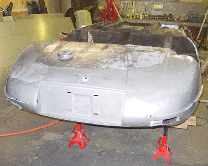
Right floor installed (13 February 2003)
It’s been five months since we picked up the car, and I am wondering if we are where I wanted to be with this project. I think we are close to the mark, though 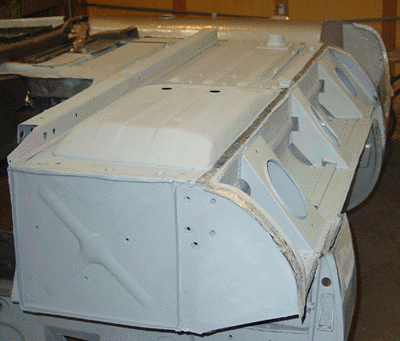 I do wish we were done with metalwork on the “tub” — the car body. We haven’t touched the bonnet, we’ve done very little with the doors and the trunk lid, and the engine and other mechanicals are practically untouched.
Getting a floor panel installed was a milestone, however. It seems a turning point from the putzy little fixes to something, well, substantial, even though the the floor panel itself couldn’t go on before the putzy little fixes were done.
Strictly speaking, the floor installation wasn’t entirely “by the book.” Rather than a simple spot-weld affair, as was the case with the original, we decided to use bolts in certain places. No bolts are on the outside edge, since that edge has to accept the outer sill. But we placed bolts (5/16″ width) at points along the edges the crossmember and along the edge nearest the transmission. Three bolts are lined up along the front tab of the floor. Along the back we installed quarter-inch bolts — a little smaller so that they fit along the back lip on the floor panel. These bolts are grade 5, not stainless; but I figured that they will be covered with rust-preventative POR-15 at any rate.
Installing the bolts makes spot welding easier, since the floor panel is held tight to the metal you’re welding to. Since the bolts are for all practical purposes invisible, I thought that this would be a good way of ensuring a tight floor fit without changing the car too much.
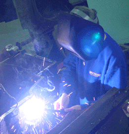
Aaron did most of the welding. After a bit of grinding to smooth out some lumpy welds, the entire surface was primed.
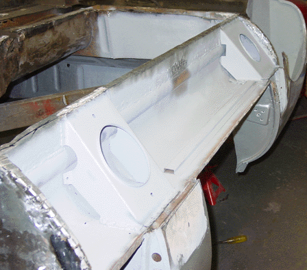
On Saturday, 15 February, we removed what remained of the left floor. In order to make sure that the floor area was structurally secure during the installation, we left square tubular beam intact on the left floor area. This beam runs from front to back along the underside of the floor. Once the right floor was in place, the support (if 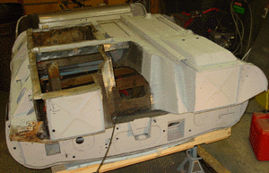 any) given to the body was no longer needed, so we cut it free and removed the vestiges of the left floor. This freed up the otherwise inaccessible space behind the interior rear bulkhead and the part of the bulkhead that faces the independent rear suspension (IRS) — a void of about 3-4 centimeters wide running laterally across the car. I vacuumed the dust and dirt that had accumulated, brushed off what I could, and Rustoleum primed the entire inside of the void. I really wonder why the car was designed to have this inaccessible area, since once the floor panels are on, you can’t rustproof or paint anything in the void.
The picture was actually taken on 16 February, after I had primed the left sill interior. (You’ll see the unprimed left sill below.)
We also did some repair of some hacked up section of the bell housing/transmission cover. This was a repair stupidity like the one we removed and repaired earlier, though the affected area was much smaller. Like that other section on the opposite side of the car, this area had been cut with a pneumatic cutter, splotch welded and then smeared with Bondo over fiberglass screen. It was nice to get real solid metal in the area. We also added some metal tabs along the perimeter where the floor panel rests. Actually the tabs we added are too large, but we will cut them to size when we’re ready to attach the floor with spot welds and bolts.
It’s coming along.
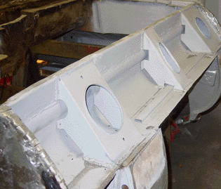
Left sill stiffeners
I had finished the rebuilding of the inner sill in late December, as I recall, but the sill stiffeners weren’t done yet. I kept the remains of the stiffeners and these made good patterns — at least for the sections that hadn’t corroded. As I have with other parts I’ve fabricated, I made a cardboard template 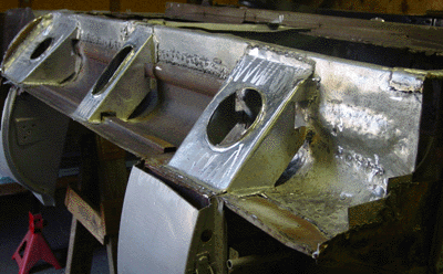 and used it to fashion the piece. The stiffeners were made from 20-gauge steel, and I fashioned the middle stiffener from the design I used for the middle stiffener done for the right sill. The secret is to be generous in your measurements for the tabs that you use to weld to the sill. It is easy to cut metal away, but not so easy to add it.
This definitely looks much improved over the way we found the sill back at the end of November. There is still a fair amount of rebuilding to do. The attachment piece for the front frame at the front portion of the inner sill needs to be completely rebuilt — and solidly because of its role in supporting the front end. I’ve decided not to use fabricated sheet metal at all for this (as was the case for the original). We’ll put together something with fortified angle iron which is thicker and stiffer than the original part. (Besides, I have the material on hand!)
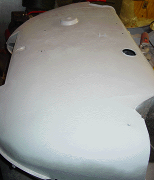
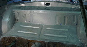
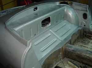
POR-15 applied to trunk (14 February 2003)
This trunk seems to have taken longer than I expected — at least it seems to occupy a fair number of these web pages. I’m hoping this picture will do it for a while for the trunk. I applied the silver POR-15 over the primer, and it looks really good. That POR-15 is really solid stuff, and I am impressed with it. I have to admit that I am not impressed with the recommended way of applying it, since the surface preparation never seemed to me to go just right. I would run into small sections (smaller than the width of a pencil) that would seem to resist POR-15. I decided it would be easier, and probably just as good, to prime the clean surface with Rustoleum primer and then apply the POR-15. This seems to work very nicely. The POR-15 bonds to the primer very well, and surface preparation is much more straightforward, not a chemistry experiment.
Saturday, 15 February, is supposed to be warm, though rainy. Temperatures in the “Cat Cage” were around 60 degrees most of the day, and so doing the painting was quite comfortable. POR-15 actually sets more quickly when the air is more humid, since the substance actually uses moisture as a hardener. Normally, I don’t like to paint in temperatures below, say, 65 degrees, but this worked out well.
The paint cured overnight to a hardness that feels very much like a “powder coating.” I am tempted to spray it and perhaps use something other than the “silver” brand. I’ve heard that the sprayed clear POR-15 dries very smoothly and is used as a primer coat for that reason. I am planning on coating the inner sills and stiffeners very well — probably a triple-coat of silver, just to ensure that the inner sills are well sealed from any moisture that might get into the area.
 place, too. I reprimed the mounting cap and the area on the floor panel where it attaches. I used stainless steel hardware to attach the piece. Once it was fitted, I saw to it that the floor panel fit onto the frame well. I’ve decided to spot weld the panels after securing them with nuts and bolts. That way I can be assured that the panel is tightly affixed and the spot welds are firm. Bolts will go on the front of the panel, along the bell housing and transmission tunnel, and across the cross beam. The seam where the side outer sill attaches will not have any bolts, since it is easily visible from the side of the car, and the outer sill itself overlaps the floor panel. I don’t want to have to cut out clearances for bolts along the edge of the outer sill, and I don’t care to drill holes through the outer sill. Both of those seem to invite moisture and eventual rust.
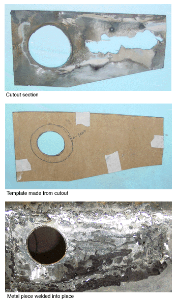 This fix was quite simple because the piece itself was flat, for the most part. The only complication was the hole for the fuel tank cannister that holds the fuel filter. I believe this part of the tank might be called the “sump.” The hole was flared, so there was some bending and stretching of the metal. I marked off the area to be cut out of the trunk floor and cut it with an angle grinder fitted with a steel cutting blade. The cut out piece quite literally served as the template for the template that I made out of cardboard from a case of soda cans. Really any flexible cardboard would do. Soda can cases are good because they have generous sides and are large enough for fairly good sized templates. (They are also plentiful in our household!)
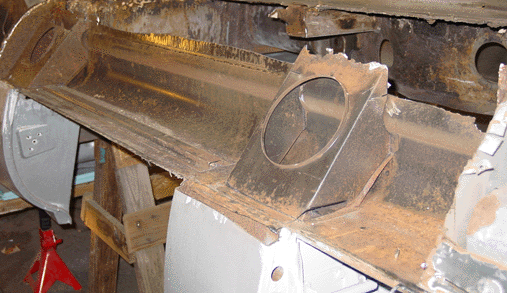 weekend, when we cut the hole clean and ground off the tabs left from the old rusted out outer sill. The corrosion on this sill was mainly in the front, with some rust buildup at the rear of the sill, under the rear stiffener. As with the right sill, there was corrosion nearest the floor as well (in the picture that would the the top edge of the sill, since the car is upside down). I went ahead and took off the rusted section all along the sill, so that we can repair the sill as one piece rather than in smaller sections. It seemed to me that an integrated repair would be more durable. This repair will be very similar to the
  You might recall that
 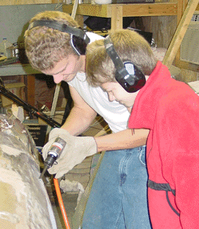 body panel, but the bottom portion did not. At the bottom edge, the metal was sticking out about 2 centimeters — a significant bulge to finesse with Bondo. I actually thought about just leaving well enough alone and using Bondo to cover the lower portion, and yet that seemed a bit sloppy. I ended up cutting off the portion of the metal that wasn’t tight and fashioning a plate to refit into the hole. I ground off the messy weld-metal, and refit the portion. It fit nicely. I then welded the two pieces together along the seam, and then ground o
 ff the excess weld. Bondo flattened it up well enough. Since the hole was inset the thickness of the sheet metal inside the trunk area, I sanded and cleaned up the area around the hole and bondoed the indent so that it is flat. Of course, the fix lacks two of the creases that are normally found on this body panel, but this fix was good enough. It is strong, and since it is covered by upholstery, it will also be invisible.
 windshield. These could not bear the weight of the body, and we made sure that theynever touched the floor as we lifted and turned the body over. This was mainly a matter of placing the rear (the so-called “boot”) of the body on a pad on the floor, then removing the support from the front. Once the entire body rested on the floor we literally rolled the body onto its side. Then after having placed the support for the front where it could accept the body and support it, we lifted the front part of the body up, leaning a portion of the body weight onto the rear section. We settled the front onto the frame support, lifted the rear section and put the supports for the rear into place.
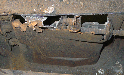 I was wrong, it turned out, since the bottom of the tranny tunnel hadn’t been well enough protected from moisture. The tunnel has a bit of an indentation on the driver’s side, where the emergency brake lever is situated. This piece contains the hinge for the lever, an electrical switch sensor that lights up the emergency brake light, and the cable housing leading to the rear brakes that are engaged by the emergency brake. (Incidently, the E-Type has a separate set of brake pads that are engaged by the emergency brake.) The bottom of the housing for the brake mechanicals and switch was completely absent — eaten away by moisture seeping and spraying from the road, presumably.
 transmission bell housing. It’s not particularly clear what exactly required such invasive and destructive work to be done. I was thinking that perhaps there was simple laziness at the root of it. For typical adjustments, the E-type has adequate portholes going into the transmission area. But perhaps this was starter work? A clutch job (unlikely, I think)? We shall probably never know.
 Anyway, I fashioned a replacement piece for the front engine/transmission housing wall out of 18-gauge steel, and I cut out the damaged piece from the transmission cowel. That piece we replaced with another piece of 18-gauge steel. Aaron did the welding and the grinding.
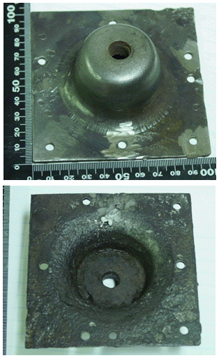 the existing cups and one of them was corroded beyond repair. I ordered a replacement for it. The other one still lingers in my mind as a repairable piece or as a replacement piece. We did go ahead and repair the cup that still has structural integrity, though questions remain because of the threading in the center of the coupling. They are not exactly well defined. I could, perhaps, go ahead and retap the threads with some success. At this point, we are going to wait until the new part arrives (sometimes after the Thanksgiving Holiday, I was told) and then we’ll make a decision about the replacement. I definitely do not want to install a restored part that will fail after a few thousand miles!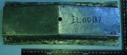
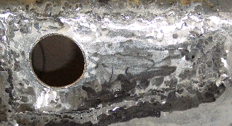 the paint from the inside of the trunk. The fix entailed cutting out the corrosion and the entire fuel filter cup hole, even though the rust damage was isolated to one side of the hole. I figured it would be easier to create an entire hole than it would be to try to fashion a piece and attach it flawlessly to the “good” metal of the original hole. Once again, this was a matter of exactly fashioning a replacement piece, welding tabs to the hole, and welding the new piece onto the tabs.
 more than brackets that fit below the door frames — below the “B”-pillar in the rear and below the structure that holds the door hinges. They turn the (roughly) square sill into two triangles, and that’s why they are so good at stiffening the sills. I was thinking about putting a third sill stiffener in between the front and rear stiffeners, but after I got them in, it seemed as though there really wasn’t that much room between the stiffeners. At least not much to worry about. (I have seen a third stiffener installed by some restorers. They use a modified front stiffener.)
 After I installed the floors I was hoping to be able to install the “radius arm mount cups” — little fittings that hold the arms that come front from the independent rear suspension. But, the mounting cups need to be put into place before the floor goes on. Some of the holes intended for hardware are not accessible after the floor is fitted, since they are then entombed in the rear bulkhead. So I have to get at least one new mounting cup, possibly two. The mounting cup that we removed from the right side was damaged by the cutting tool, and it was at any rate pretty badly damaged by rust.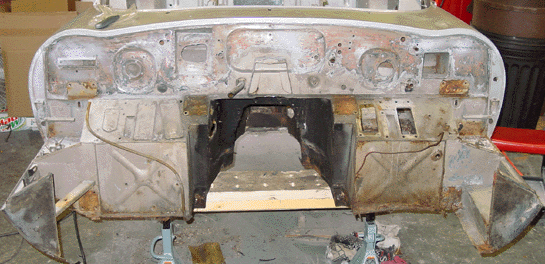
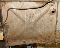 Thus, the directions get reversed. You always refer to the sides of the car as though you were in the car seat, looking forward.) The piece was bent on the bottom, and corrosion had significantly weakened the metal up a little less than an inch. The picture clearly shows the bend, and some rust is visible, though much of the rust is surface rust and not a concern.
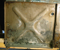 of the footwell with spot welds and lap welds. This lower section has a tab that angles out from the front, and it is part of the way that the floors are attached. As we did with the left inner sill, we used 18-gauge steel to fashion the pieces. It’s not too tough to cut, but it is stiff and resists the bending. To make it easier to grab and bend, I made the tab about three-quarters of an inch big. Although the final product doesn’t need that big an angled tab, we can cut or grind off the excess after the floor panel is in place, too.
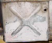 and start doing everything with bondo.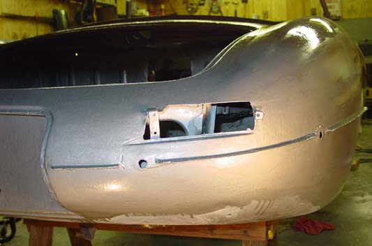
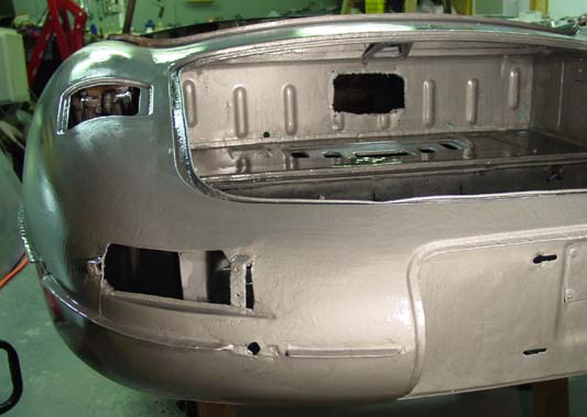
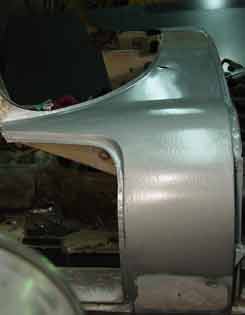 version of the product, evidently. I do not believe that the Jaguar I have “needs additional strength” but I figured that some additional metal wouldn’t be that bad after all. The trouble with the “silver” product seems to be that it is harder to apply. It dries to a less than smooth surface, so you have a bit more work to do in smoothing everything out. In the case of this restoration, I wasn’t too worried about smoothness, since I have some work yet to do on the body, so reinforcement sounded good.
 The lower section of the top part of the bulkhead cover — that is, the area where the outer sill meets the body panel — I have left alone. I am concentrating on the upper sections of the body, since it will be easier to do the lower “hemisphere” of the body when I have flipped the body over. I will do the body work in the lower section after the outer sill on this side is installed (and on the other, most probably).