Color on front frames
First, a larger picture than I usually post. I beg forgiveness for the size of the shot, but I figured the compressed GIF image sacrificed too much accuracy in color. Fatter JPEG format will do.
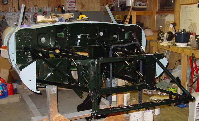
The picture shows the color a bit more clearly than the previous shot did, but still the photograph doesn’t quite do opalescent dark green justice. It is indeed more fiery than the flat web browser allows.  You can probably see the strategy I am taking in rebuilding and spraying color. I am holding off with exterior sections of the car until the internal sections are more or less complete. This has the upside of allowing me to get a little better with the spray gun before I attempt shooting color on the parts of the car that are most easily seen — and therefore more sensitive to my ineptitude with the sprayer. It has the downside of making any painting a big deal, since everything needs to be masked and cleaned and fussed over. Doing the entire job in one fell swoop would be more efficient, perhaps.
But if I were worried about efficiency, I wouldn’t be restoring this car, now, would I!
The primed front frames were sprayed with sealer and then color was applied. They were sprayed separately and then assembled onto the firewall (front bulkhead). I had replaced most of the bolts and nuts with grade 8 hardware, replated with zinc and then treated with zinc blackener. The effect is quite nice. I decided to give the blackened zinc a try in spite of the hours I had spent doing the nickel plating the front suspension parts. The additional protection was nice, but using correct color bolts convinced me.
As a small aside, I should add that I have been seeking opportunities for practice with the spray gun. Well, sometimes they have found me, too. The boys managed to wreck the 1995 Dodge Ram pickup so that the insurance company totalled it — it doesn’t take much to total an old vehicle, even a truck. I settled for enough to get another old pickup (a Ford F-150) and I decided to keep the Ram. We fixed it with some pulling and sanding and new parts, basically the driver’s side front end. Mechanically the old thing is still in great shape, and the frame wasn’t harmed by the accident. This turned out to be a great opportunity to practice painting. It was, unfortunately, as hard as I remembered. The old truck looks good from 20 feet, but you do see a couple of runs if you stand much closer.
Oh, well, so long as it doesn’t happen on the Jag….
Front suspension rebuild started
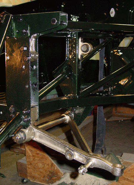 I thought about calling this section “Sproing!” because of the trouble I have had with the upper wishbone “circlips” (also known as “snap fasteners” or “internal retainers”). I got new upper and lower ball joints/ball pins for the wishbones, and the upper kits were supposed to have included internal retainers. And one kit did, but the other replaced the internal retainer with an external retainer, which of course wouldn’t work at all. I fetched the old part that I removed that had the internal retainer and I figured I was set.
Never underestimate the power of tools that aren’t quite suited to the purpose.
I managed to let both of the good circlips fly off into the netherworld. In the vain hope that cleaning might scare up one of them at least, I grabbed the broom and swept the garage. No clip appeared. The second one flew off after I had opened the garage door to let light come in so I could search for the first lost circlip. Of course, it flew off into the rose garden and grape arbor with a sleek and fast zing. I told Aaron he could grab his metal detector and search, but he wasn’t motivated.
McMaster-Carr came to the rescue, and I will be expecting a box of 25 circlips sometime early next week, I suppose. That should give me enough circlips for, well, another eleven cars. Anyone need a circlip cheap?
Besides this little annoyance, there are others. I’ll be compiling tips for installation of the front suspension parts to publish later, probably in the next entry. It turns out that order of rebuilding and installation matters a bit, but it’s not complicated.
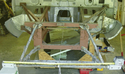 which probably sustained some accident damage. (My initial observations, including a description of the way the damage was “repaired” or at least hidden, appear in a
  holes that are designed and intended to be used to make minor adjustments to the fit. But this catalogue is a good reference to have on the shelf. Terry’s Jaguar Parts has a good reputation as a parts supplier. They’ll send you a catalogue if you ask.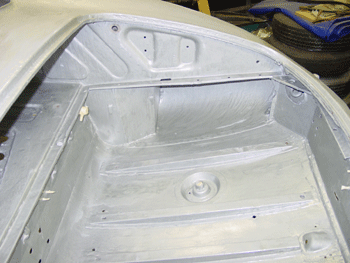
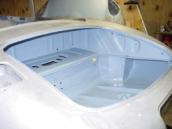
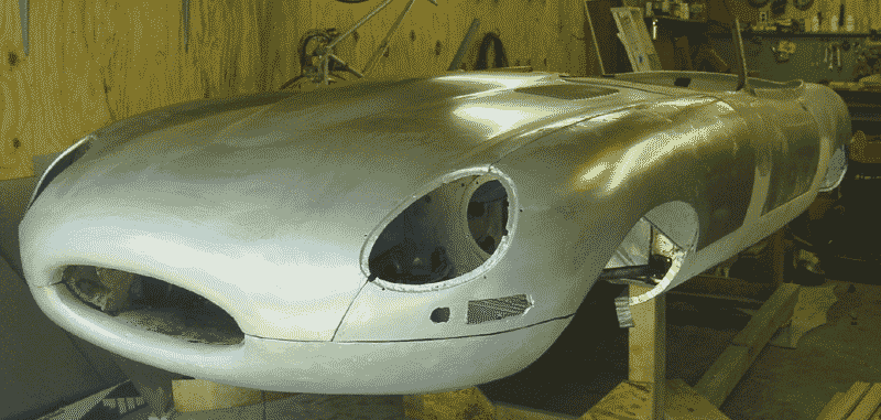
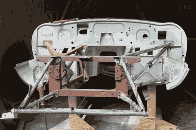 though I still haven’t glued the bonnet pieces together, I figured this would be a good time. As a matter of fact I was hoping that fitting the bonnet to the frame would help clarify any adjustments that I might need to make to get the bonnet internals ready for the adhesive. I crudely tacked the bonnet internals together with some of the bolts and screws and “oval washers” — but I hadn’t by any means fit them all.
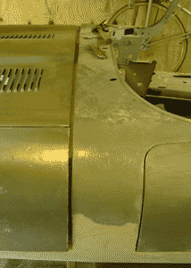 and attach, but the other side (the left) needed a bit more coaxing. Even from the gross fitting, it was apparent that the gap between the back of the bonnet and the body shell was simply too big to surmount. This was especially the case on the right side of the car, where the gap is almost two centimeters wide. On the left side, the gap is almost a normal size, though the bonnet appears to be pitched a little toward the left. Also, the gap was large to begin with, so the only adjustment we could make was to draw the bonnet forward by tightening the hinge bolts. But, of course, they only tighten so far. I believe the usual adjustment is expanding the fit of the hinges to the bonnet — in effect loosening the hinge bolts. This is done with shims. The use of shims helps to widen the gap where bonnet and body meet, and heaven knows we don’t need it any wider there!
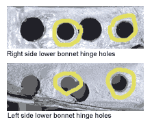 This is where some odd holes I noticed come in, along with the benefit of taking lots of photographs of the car at disassembly.
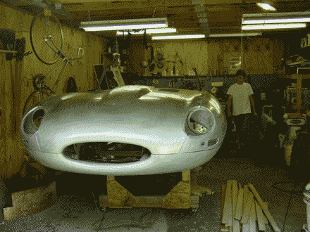 quite apparent. Then I’ll have to repair those silly extra holes!
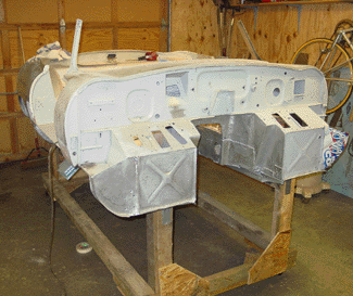 building such a fancy rotating mount for the car. I suppose it would be nice, but we’ll flip this car over as need be. That said, I did need to create something to make it easier to move the body out of the way when we weren’t going to be working on it. I used lumber we had saved from an old chicken coop and four middle duty casters from the lumber yard to build a rolling rack. It stands about two feet high, and it carries the car quite high — perhaps a little too high. But it’ll do. And it was really nice to be able to roll the car body to the side to sweep the floor and clean up. It’ll practically be necessary once we need to move larger parts (like the bonnet) out of the garage to work on. The fact that it’s fairly high is also a nice feature, since I won’t have to be bending down all of the time to work on areas in the interior.
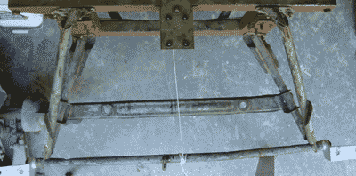
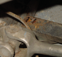 spanning the gap between the two side frames) was rusted through on the bottom. And a section below the battery area, on the underside of the tube, was rusted clear through. This damage wasn’t apparent from the top of the vehicle, though when everything was flipped over it was very easy to see.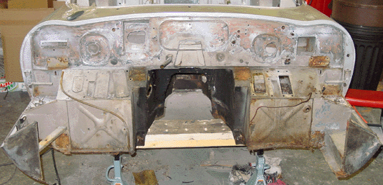
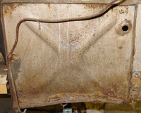 Thus, the directions get reversed. You always refer to the sides of the car as though you were in the car seat, looking forward.) The piece was bent on the bottom, and corrosion had significantly weakened the metal up a little less than an inch. The picture clearly shows the bend, and some rust is visible, though much of the rust is surface rust and not a concern.
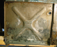 of the footwell with spot welds and lap welds. This lower section has a tab that angles out from the front, and it is part of the way that the floors are attached. As we did with the left inner sill, we used 18-gauge steel to fashion the pieces. It’s not too tough to cut, but it is stiff and resists the bending. To make it easier to grab and bend, I made the tab about three-quarters of an inch big. Although the final product doesn’t need that big an angled tab, we can cut or grind off the excess after the floor panel is in place, too.
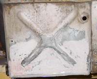 and start doing everything with bondo.