Engine in place
I wanted the engine to go in this fall, and it did! Aaron and I fiddled with the fit of the torsion bar reaction plate — the bane of the removal of the engine renewed in reverse! — and the next day slipped the engine into place. Here’s how it looked just after it was put into place.
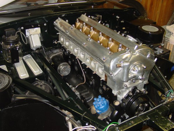
The actual installation was on my birthday, so it was a very good day. As a matter of fact, I think it was my best birthday in years.
Aaron and I dropped the engine in from the top. Bill McKenna opted for the bottom, and there is some feeling that the bottom-up method is easier than dropping the whole hulk from the top. When we took out the engine the first week we had the car (over five years ago!), we lowered it and lifted the subframes to allow us to pull the engine and transmission forward. I recalled fighting with the motor mount brackets to get them to clear on the way down, so this time we put the engine in from the top. My father had warned about chipping the paint on the subframes, and so we put a couple of layers of masking tape on the frames. 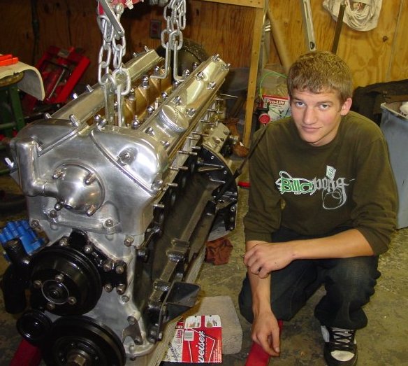 The tape did provide protection from the inevitable bumps.
It is a fairly tight fit from the top, and you do have the raise the engine high enough that it feels a little scary. The touchiest part is tipping the tranmission end down, though the hoist we have includes a nifty worm-geared adjustment that makes pitching the engine angle a matter of turning a crank. The process of setting the engine into place really amounted to easing it into place by gradual leveling of the engine and lowering it in steps. We did have some extra — perhaps even necessary? — wiggle room because we did not have the crankshaft pulley attached to the crankshaft dampner. (I actually haven’t bought it yet.) This meant we had a couple centimeters to play with when the oil pan was just below the top of the picture frame.
Not only has the engine changed…
It’s fair to say that the engine would still be sitting on the floor in front of the car were it not for Aaron, who worked to resolve some of the fitment issues that I had wrung my hands about over the past several weeks. Literally, I had fretted about things so much that I had avoided doing much to resolve the issues.
Well, I had actually fretted not so much about things in plural as a specific thing: that terror-inducing construct having to do with the torsion bars. As I’ve said before, I hate torsion bars. And our experience five years ago with the torsion bar reaction plate still is amazingly fresh in my mind. The thing was a beast to get off, especially since we were cramped under the car and hadn’t really too deep an understanding of the dynamics of the front suspension. The role of the reaction plate in the front still seems a little mysterious to me, since it has been claimed that the reaction plate actually imparts something between the two torsion bars, allowing them to communicate in some advanced engineering sort of way. Perhaps. All I know is that the plate goes in after the engine is in place, and the plate either fits or it doesn’t, since the fittings just won’t give.
To make sure that the reaction plate was going to fit, I actually used it to set the location of the two halves of the replacement floor (right and left), but that was before the POR-15, undercoating, primer, and paint. The coatings made 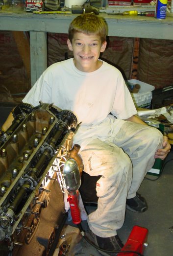 enough of a difference that additional futzing was required. Believe me, it takes very little to make the reaction plate tighter than works well. Bill McKenna had to do the same, he reported, though he used a grinder to take off the excess powder coat and such. Aaron and I didn’t resort to that, but we did whack and bump a fair amount. I suspect that professionals might actually take better account of the coatings when they use the reaction plate to fit new floors. I didn’t think of that when we were installing the new floor panels.
It’s important to get all of the bolts fitted without having to contend with the engine and transmission, so if you’re doing a restoration like mine, fit the reaction plate before dropping the engine in. That little extra time will take hours off the work.
We took the tension off the torsion bars, of course. It actually isn’t that bad a job to do, but it is a hassle — seems too much a sideline in relation to the real show of the engine going in. And, of course, there’s no graceful way to get at the bolts for the torsion bars and the reaction plate once the engine is occupying all that space.
I was struck at how much Aaron has changed from the time when we first took the engine out (and he had managed to mangle a bronze bolt or two) and the time when we put the new engine in. Pictures say it all. He’s grown up to be a handsome man.
I’m now beginning to collect the parts I need to do all of the cooling and fuel and ignition work. Cooling hoses are the first thing on the list. I’ve found that bringing the old hoses into the parts shop works just fine. Gates replacement hoses are available, and Mike Frank has published a list of them. I’ll add to the options with another list in the near future. Several of the old hoses are either Jaguar replacements or (heaven forbid!) the originals. They’re in pretty tough shape.
 itself. The “skin” of the left door looks quite good. The lower section where the internal box-like door body attaches to the external metal sheet was a little rusted, with a few small corrosion holes poking through. But the metal resisted pressure all right, and we will go ahead and repair the corrosion from the inside of the door. I suspect that the doors corrode in that section because of the weird way that moisture is handled. Water that spills from the body on top of the door falls through a small drain hole, and that drain hole spills into a rubber hose that diverts the water around the internal section of the door hinge attachment inside the door panel. But the strange thing to me was that the hose simply dumps water into the door panel. I would have thought that the hose would have diverted the water all the way through the door to an external hole. As it was originally designed, the water flows into the door panel and then out through two slits on the bottom of the door. The effect is that water can easily collect inside the door panel, and may even be retained by the anti-drum material fitted inside of the door. This material looks like a rubberized felt, but it seems to be still somewhat absorbent. I will probably just replace the hose as I found it, but I have thought that maybe I should alter the door a bit to give the water flowing in a more direct way out. The interior of the door panel will at least be well rust-proofed, so the next generation can renew the door skins if they need to.
 building such a fancy rotating mount for the car. I suppose it would be nice, but we’ll flip this car over as need be. That said, I did need to create something to make it easier to move the body out of the way when we weren’t going to be working on it. I used lumber we had saved from an old chicken coop and four middle duty casters from the lumber yard to build a rolling rack. It stands about two feet high, and it carries the car quite high — perhaps a little too high. But it’ll do. And it was really nice to be able to roll the car body to the side to sweep the floor and clean up. It’ll practically be necessary once we need to move larger parts (like the bonnet) out of the garage to work on. The fact that it’s fairly high is also a nice feature, since I won’t have to be bending down all of the time to work on areas in the interior.
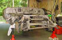
 spanning the gap between the two side frames) was rusted through on the bottom. And a section below the battery area, on the underside of the tube, was rusted clear through. This damage wasn’t apparent from the top of the vehicle, though when everything was flipped over it was very easy to see.
 welding, and Aaron did the welding, for the most part. As I said in the
  of the panel (along the seam of floor panel and outer sill) had a very natural fit. We basically just laid the panel on the car and welded. However, the central portion of the panel (behind the cross member where the right and left floor panels meet) seemed to bulge a bit. We will bolt that area in any case, and probably weld it as well. As I recall, the original floor panels had a separate panel attached in this area, which is the part that forms the “floor” of the drive shaft tunnel. I don’t know that this original panel was an original part, in any case. (I haven’t look at the notes or at the parts themselves, but this piece may actually have been something other than metal.) The pictures I have seen of this area don’t show a metal cover over the area. And yet, a sheet covering the area where the floor panels meet actually doesn’t sound like a bad idea.
 interior meets the lower edge of the convertible top. This area has been badly corroded, and crudely “fixed” with Bondo and wood strips (!). We had removed this blodged repair, and intended on doing some metal work. That we did, with two pieces of 20-gauge metal. The first piece was aligned with the curve of the upper portion of the left rear quarter panel, and the second piece (welded on top of the first piece from inside the wheel well) formed the fillet wall. As with other fixes, we ground off the welding excesses, and used Bondo to smooth the surface. We were actually less worried about how this fix looked, since it is in a place where you really need to want to look to see it at all. After the application of Rock Guard to the area, this fix won’t be easily visible. But trained eyes will see it, I guess. If they look for it….
 body panel, but the bottom portion did not. At the bottom edge, the metal was sticking out about 2 centimeters — a significant bulge to finesse with Bondo. I actually thought about just leaving well enough alone and using Bondo to cover the lower portion, and yet that seemed a bit sloppy. I ended up cutting off the portion of the metal that wasn’t tight and fashioning a plate to refit into the hole. I ground off the messy weld-metal, and refit the portion. It fit nicely. I then welded the two pieces together along the seam, and then ground o
 ff the excess weld. Bondo flattened it up well enough. Since the hole was inset the thickness of the sheet metal inside the trunk area, I sanded and cleaned up the area around the hole and bondoed the indent so that it is flat. Of course, the fix lacks two of the creases that are normally found on this body panel, but this fix was good enough. It is strong, and since it is covered by upholstery, it will also be invisible.
 windshield. These could not bear the weight of the body, and we made sure that theynever touched the floor as we lifted and turned the body over. This was mainly a matter of placing the rear (the so-called “boot”) of the body on a pad on the floor, then removing the support from the front. Once the entire body rested on the floor we literally rolled the body onto its side. Then after having placed the support for the front where it could accept the body and support it, we lifted the front part of the body up, leaning a portion of the body weight onto the rear section. We settled the front onto the frame support, lifted the rear section and put the supports for the rear into place.
 I was wrong, it turned out, since the bottom of the tranny tunnel hadn’t been well enough protected from moisture. The tunnel has a bit of an indentation on the driver’s side, where the emergency brake lever is situated. This piece contains the hinge for the lever, an electrical switch sensor that lights up the emergency brake light, and the cable housing leading to the rear brakes that are engaged by the emergency brake. (Incidently, the E-Type has a separate set of brake pads that are engaged by the emergency brake.) The bottom of the housing for the brake mechanicals and switch was completely absent — eaten away by moisture seeping and spraying from the road, presumably.
 transmission bell housing. It’s not particularly clear what exactly required such invasive and destructive work to be done. I was thinking that perhaps there was simple laziness at the root of it. For typical adjustments, the E-type has adequate portholes going into the transmission area. But perhaps this was starter work? A clutch job (unlikely, I think)? We shall probably never know.
 Anyway, I fashioned a replacement piece for the front engine/transmission housing wall out of 18-gauge steel, and I cut out the damaged piece from the transmission cowel. That piece we replaced with another piece of 18-gauge steel. Aaron did the welding and the grinding.
 the existing cups and one of them was corroded beyond repair. I ordered a replacement for it. The other one still lingers in my mind as a repairable piece or as a replacement piece. We did go ahead and repair the cup that still has structural integrity, though questions remain because of the threading in the center of the coupling. They are not exactly well defined. I could, perhaps, go ahead and retap the threads with some success. At this point, we are going to wait until the new part arrives (sometimes after the Thanksgiving Holiday, I was told) and then we’ll make a decision about the replacement. I definitely do not want to install a restored part that will fail after a few thousand miles!
 the paint from the inside of the trunk. The fix entailed cutting out the corrosion and the entire fuel filter cup hole, even though the rust damage was isolated to one side of the hole. I figured it would be easier to create an entire hole than it would be to try to fashion a piece and attach it flawlessly to the “good” metal of the original hole. Once again, this was a matter of exactly fashioning a replacement piece, welding tabs to the hole, and welding the new piece onto the tabs.
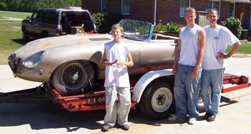
 the D-type, which won the Le Mans in the late fifties. That car was of tube construction. The E-type we are familiar with is partially tube construction (the area in front of the “bulkhead” which begins in front of the dash) and partially structural sheet metal construction (everything else behind the dash). This is an enormously strong construct.
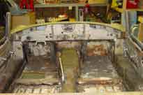 The outer sills got rusty, so they were replaced. The trouble was that the areas behind the outer sills and internal to the sill structure overall were (probably) ignored. Because the inner sills lay behind coverings of the interior or were less easily accessible, they were ignored. In short, the trouble is there, but it’s harder to see and harder to repair. Deterioration of the inner sills became apparent after we removed the interior trim — the carpeting (such as it was) and the felt padding. Rust damage was especially bad in the front left foot well inner sill. It’s not clear in my mind whether the entire inner sill on the left side will need replacing. I am now thinking that it will not, though repair is required. The final verdict will be clear after sandblasting.
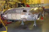 were rusted through and repaired with bondo. We’ll fashion a metal replacement, of course. Other rust damage in the rear was related to the deterioration of the sill: the rear quarter panel on both sides were bondo-ed — perhaps the most shameful of the early repairs, since the bondo hides a multitude of sins. The areas immediately behind that bondo were in bad need to replacement. We will tear that bondo out (as we will do with all the bondo) and probably open up the rear quarter panel in that section. This will allow us to replace the internal structure.
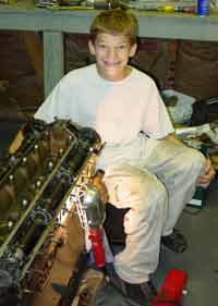 cutter. We had trouble loosening the top two timing chain sprockets, but we circumvented that by removing the cam shafts. The cam shafts look quite good, and their bearings look practically new. The valves show some normal wear and tear, but none is compromised with a blow hole. Pistons are blackened, but everything moves nicely in the cylinders. We haven’t removed the oil pan to look at the connecting rods and the crank shaft.
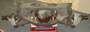 could wrestle enough room to remove it. (This was one of two big black spiders we ran into.) It dropped like a charm. Read the shop manual instructions carefully to get the details on easy removal.