Category Archives: Body work

December 2015 – Convertible top replaced

People might recall that my canvas top got ripped when I put the top down for the first time — two five-inch rips radiating from the rear corner of the door windows. Clearly, I had done something wrong in the initial installation, and so I did some problem solving and discovered the issue. In essence two things happened:

  • I didn’t pay enough attention to the physics of the matter, since the metal frame and the “bows” fold in a certain way. That moved two points apart in a manner that my gluing job on the top was strained until it failed — in effect removing the stress by ripping the material apart.
  • I misinterpreted the way that tabs on the canvas top were to be used. I figured they were tabs for gluing onto the frames above the door windows, but that was wrong. The gluing actually fixed the two points on each side of the canvas top that the frame moved farther apart when it was folded down. The gluing set the ends of the stress that the folding brought about.

Here’s a video that shows the action of the frame — and why the top tore. Note the way that the top end of the rear-most window frame piece separates from the rear end of the piece over the window. There is a short piece that bridges these pieces of the frame around the window. Initially that short piece separates the parts I glued by about four inches, but when the frame is put down, those pieces set about a foot apart.


Here’s a picture of the fateful tab on the torn canvas top, labelled as “The tab I glued, but shouldn’t have.” I really don’t know why the manufacturer of the canvas top would have included a tab at that position, since it quite obviously fit the frame piece above the window, and it seemed designed to be attached. On the retorn_canvas-151229
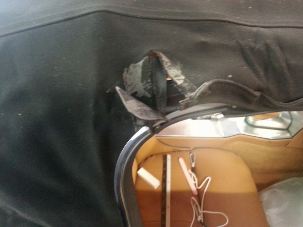
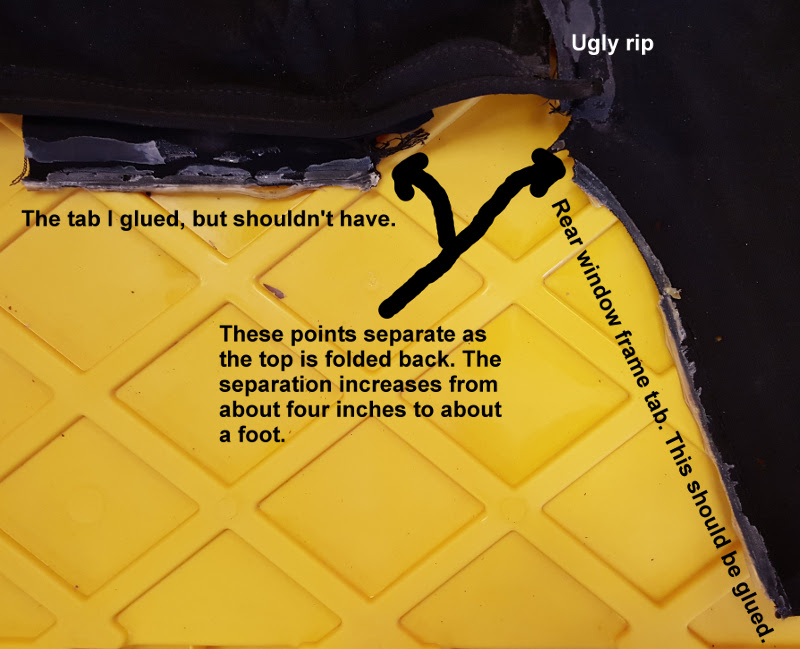
placement (vinyl) top I got, the area above the window frame was reinforced with a vinyl piece about the size of the tab I had fatefully glued, so it could be that the manufacturer of the canvas top wanted the tab just tucked back as a floating protection for the top above the window.

In any case, there was no arguing with the physics of the thing. It tore. The video and the picture should tell the story.

While I was investigating the reason for the failure of the canvas top, I revisited “andyzaks” instructions that I found on E-type Lovers (http://www.xke-lovers.com/). These are good instructions, and I followed them through again — in dry run fashion — to see where I might have diverged and made my error. I came to the conclusion that I was misled by the “fateful tab” that apparently didn’t even appear on andyzaks’ top when he was putting his on. Key thing to note is that the tops on the Series 1 cars are fastened at the front, back, and at the rear of the window frame, where the chrome finisher sits.

I decided to do a video of the process, and it came out pretty well, though I realized after going through the whole exercise that doing a video is harder than writing up a blog post! If you listen closely you’ll probably hear Christmas music in the background at times. That’s a dead give-away for when this top was installed!

The car is going on the market in late January 2016, very likely. I have been planning for this, and I’m getting to a point where I think I have a realistic plan in mind. I do wonder about selling it when I take it on my little drives around Rougemont, but I think I want a new project to sink my teeth into.

Oh, I think I’ll do a few more videos as time goes on.  Videos are an interesting medium, even though they are a little more tedious to put together.

August 2014 – On the road again

Yes, it’s been a long, long time. I had been so good about recording things on this blog. Then, when the car came darned near completion … well, I pooped out, preferring to sit in the old thing and tinker or just listen to the engine and watch the gauges. The restoration journal never got an update.

Well, I’m back now. The interceding years — it’s been since June 2011! — won’t be covered in much detail, but I’ll do what I can do.

A first trip? To the gas station, of course!

The big news is that the car is on the road, fully licensed and insured (I went with Hagerty). It’s been legal on the road for over two years now, and I’ve driven a grand total of 110 miles. The initial voyage was about a mile up the road to the Rougemont BP. Arlene came with, and the car ran … horribly. It sounded like a tractor (related details below) and it had very little power. It also sucked gas, so it was fortunate that we went to the gas station.

In a restoration, you always do some things twice and a few things more than twice.

In the last (now ancient) update, I mentioned that I had installed the convertible top. It fit snugly and well, I thought. But I must have done something wrong, since the darned thing ripped at two symmetrical points when I retracted the top. I still do not exactly know what the problem was, except perhaps that I had installed the top too snugly or that I had attached the top to the frame pieces inappropriately. The tension points appeared in the upper rear corner of the retractible door window frame, and I suspect that this area may be installed loose? I notice now that there was a cord sewn at the end of the rain trap immediately above the window frame, and I wonder if that was actually supposed to be the attaching point for the top at some point. I have to re-read the instructions I used to see if there was something I missed or misunderstood.

I did try patching the tear, but it was not suitable, and in any case the patch came off the first time I retracted the top.

At any rate, a new top is in order, and I think that I will probably go with a vinyl top — which, I am told, is more original. My eldest son, Derek, has a Honda S2000 (very nice car, by the way, and one that I have autocrossed), and it has a vinyl top. It is quite nice — and actually much nicer than I recall my older vinyl top was on the MG I had in college.

Doing things over is all part of doing a restoration, either because things don’t go back together as you’d think or because, well, Stuff Happens. People might recall that Bill McKenna began his restoration about when I did and also chronicled his progress for all to see on the web. (He finished his car quite a while ago, and it is marvelous.) He had redos and mishaps just as I did (as with the doors). I think you have to be a bit Stoic if you’re going to take on a restoration and actually complete it, since progress gets interrupted and sidetracked.

Then, there are the torsion bars on these cars. They are the best instructors of patience, persistence, and fortitude.

Mo-Ma comes through for another delighted customer

Mo-Ma Manufacturing in Albuquerque, New Mexico (www.momamanufacturing.com) was my choice to get the old tachometer upgraded. I had removed the tach generator when the engine went in. I recall discussions on forums about the “dog” that drives the generator being flimsy and breaking and then falling into the oil system, threatening to jam pieces of itself into the oil pump. That didn’t sound good to me. Besides, the technology has improved quite nicely, so that driving a tech off a coil is simple and accurate. Mo-Ma has a great reputation for workmanship and, as I learned, for customer service. I can’t recall the lady’s name I talked with, but we had a delightful and wide-ranging conversation. She has been in this business for years, starting off being the Smith’s representative for the Western United States.

(I did follow up a few months after I got the tach back, only to learn that Margaret had died.)

I sent the tach in, and I promptly got it back, all cleaned up and beautiful. It works beautifully.

The business of restoration has a few characters who stand out, and I have to say that the woman who I talked with at Mo-Ma is among them. I recall Mike Moore (the one in California who’s an enginer, not the film-maker) reporting that he had a nice telephone conversation with her, too.

Exhaust pipes. Mufflers. Nicely chromed resonators.

From summer 2013 to early 2014, the exhaust “system” consisted of a pair of Cherry Bomb glass packs and 2-inch conduit I had bought from Lowes and bent into shape in the old cramped garage. Or there was nothing at all from the manifold back, since I tired of the rudeness of the noise and removed the improvized exhaust system. I was set to get the Real McCoy. And so the car sat, sadly, waiting for a refresh. I bought the paired mid-car mufflers (Walkers, for those who are interested) and the resonators along with mounting hardware. I installed the mufflers and had the resonators ready, but I still hadn’t acquired the connecting pipes. I even ordered them, but found out in a phone call that they weren’t on hand. “Really,” the fellow said, “just go to a custom exhaust shop and get some made. They’ll cost about the same.”

Made sense. I cancelled the order. But … I procrastinated.

I had the fellows at REMCO Muffler Shop in Roxboro, North Carolina, do the pipes, and they did them well and with care. I actually made the decision to go with them after I learned that they had done work on an old ’50s-era DKW. I figured if they would do that well (and the customer was very satisfied), an old Jaguar might be interesting to them and that they knew how to treat on old car with respect. They did a beautiful job, and they were great fun to work with on the project.

And now there is a Garage Mahal — and maybe time for a different project?

Most of the restoration of this 1963 roadster happened in pretty cramped quarters, made even more cramped by my inherent resistance to putting things away. Of course, there wasn’t much space to put things away in! Fixed that.

We built a three-bay, high-ceilinged, well outfitted garage and kept a journal of the building on my tumblr site. Garry Whicker from Hillsborough, North Carolina, was the general contractor, and he ably rounded up the talent and efficiently executed the construction. It was great fun to see going up! And it has been a great thing to see how well it’s been used by my now grown-up sons and their friends. We have fixed our cars, we have done major work to “Maximum Oversteer” the now-junked Chump Car, and the young men (calling themselves Beast Mode Racing) have started a new Chump Car to debut on track next year. (See a Youtube video of Aaron driving Max at Watkins Glen.)

So now we have ample room, even for the dogs.

Bringing this car back from the brink has been enormously gratifying (at least when it’s not been enormously frustrating and challenging!). I now have a very fine car that still needs a tweak here and there, and that still requires some fettling now that it’s on the road and I can gauge performance under “real conditions.” I still have a couple of things to hook up, like the windshield wipers — which are, of course, useless anyway since the car never goes out in the rain now.

But I find that I’d like to start a new project and find a new challenge. I am nearly committed to selling the Jaguar E-type that I’ve had such fun with over the years. I wanted one of these cars since I first put together a model of a coupe when I was in fourth grade, and now having it, I find that perhaps my interest is really in the putting together and not in the possession. (Haben oder Sein, Erich Fromm once asked.) As a matter of fact, that little discovery may have been the most profound over the years.

So, who knows what will happen in coming months.

May 2011 – Top and seats

Top

David Boger (proprietor of everydayxj.com) got a convertible top frame in a deal for some old Jaguar parts back in fall 2009. I picked up the frame from him on my birthday in October, and I fetched it months later (the end of March 2010, as a matter of fact). His business and his place have really expanded, so the XJ6 crowd is now especially well served. He had (and still has) some E-type parts, too. I picked up the frame with the understanding that it was lacking one of the bows, the front one specifically — or so we thought. Since I had pieces of the original top frame, I figured that I would be able to fashion a new bow or otherwise get one. However, it turned out that the top frame was intact and was merely an early example. The early top frames didn’t have three bows, but rather just two. I’m not exactly sure when the third one was added, and Thomas Haddock is silent on the additional bow, as far as I could tell — which makes me a little wary of the truth of the matter. But on this top frame, there was no means of attaching a front bow, and there was no violence done to the tubing where a bow would have fit. The front pan-shaped metal edge of the top frame fit perfectly, and so the whole kit must be there.

I removed the old Jaguar grey and resprayed it, cleaned up the chrome bolts and supplied the few that were missing, and then I set it into place. Tops are easy to get, and I got mine from an eBay vendor. I decided to go with the canvas-like material called “Stafast.” Instructions for installation are on the web, and I went with the ones that were put together by “Andyzak” and published on E-type Lovers (http://www.xke-lovers.com) at http://www.xke-lovers.com/ragtop.htm. Follow the instructions and everything goes fine. The only trouble I had was affixing the front chrome trim at the ends, where the curve of the front seemed to work against the clips. It took some wrangling, but I got it on.

Interior (including heretical seats!)

The interior project has gone on for years, and I have an entry that goes back to “Fall/Winter 2005/2006” when vinyl and moquette were applied. As with everything in this extended restoration, I have thought and re-thought, decided and re-decided (and then decided yet again!). The interior probably best exemplified the consideration-reconsideration dynamic. Some, I suppose, would call it waffling.

I waffle on leather and commit heresy.The car seats are a case in point, and the waffling arose from the greater context of this restoration — a couple other cars. The old E-type wasn’t the only Jag in stable, so to speak. I owned until recently an XJ8L, and my daily driver is an XK8, which of course, I bought because it takes design cues from the E-type. Both have leather pretty abundantly. I found that I am not a really big fan of upkeep of leather. The XJ8L interior was nice, and the leather was supple and soft, but I noticed over just a few years that it discolored in wear, probably because colors or dyes wore off? The driver’s seat got a bit of this crumply look, too. And the interior seemed to need babying that we frankly couldn’t easily do, since our vehicles have to trek off to the barn and suffer from the insults that just come with living out in the toolies. The state of the leather in the XK8 is, to put it in a word, awful. (Now, admittedly, this is a daily driver that sometimes hasn’t had the leather conditioner applied as often as might be necessary.) I have gotten to the point that I have re-dyed the front seats, after making an attempt to repair cracks and holes in the driver’s seat cushion. The repairs have held up, mostly, and the color is … er, OK. But, in fact, I hate the leather seats in the XK8, and they’re coming out for a recover when I retire the car from daily use. My wife Arlene thinks I should just get rid of the XK8, but I have grown fond of it despite its deficiencies.

As an aside, I note, with some dismay, that the leather interior of my eldest son’s VW Passat (an older car with higher miles) is in great shape. I don’t think that’s all a matter of exquisite care, either.

This is all to say that I was less than enamored by leather due to my experience with other cars. The original plan was to get leather seats for the E-type and have them installed by a professional. I got shaky on that decision, though. I don’t want to futz with leather and just watch it degrade pointlessly, as seems to have been my experience. And, though many people get all Ricardo Montalbon about leather, I have no trouble at all with good vinyl. Not the chintsy brittle stuff, mind you, but the “pure Corinthian vinyl” that graces luxury cars — and holds up better than the leather.

So, yes, the seats are heretical vinyl. Not leather. Thank God, I might add.

A second consideration was that my seats had to be special, with green piping. This is actually not too much of a problem, it would seem, since the leathers are not mass manufactured and then piled up in some warehouse somewhere as inventory. They are cut and sewn to order. But the piping issue introduced a level of complexity to an order that wasn’t welcome — at least as I interpreted the conversations I had. And, when I broached to topic of would-it-be-possible-to-use-high-quality-vinyl … well, that was too much. One well intentioned seat provider said, “No.” That was the end of the matter.

Now, I might be demanding, but I do strive to be courteous. I didn’t get the feeling I could get what I wanted from the Usuals on the West Coast. At least my interactions didn’t inspire confidence. So, I figured, I’d go with the locals. There are two promising upholsterers in the area, and I visited them both. One has a great reputation for late model cars. Aaron highly recommended them, saying that they were quick and the work they did met or exceeded expectations. Probably so, but there was no enthusiasm for doing seats on an old beast like a 1963 Jaguar E-type. Kits only, the fellow said, and be sure that you show up with molded seat cushions. Otherwise, no go. No cutting, no sewing. The other upholsterer had done 1950s and 1960s American cars, and his work seemed quite good. I met him in front of his shop, and as he emerged from his car he carried a large pot pipe, which didn’t exactly inspire confidence. Still, he and his group seemed competent, and they were working on the Saturday I visited. We went through vinyl sample books together, and I thought there was a possibility. Alas, things moved toward the nebulous, and I didn’t want to be stuck with an unending job and interminable waiting. I’d gone through that kind of thing before.

So, I asked myself, what about doing it myself. I had most of the templates, the seat cushion notwithstanding. I never done this kind of thing before — heck, I’ve never run into trouble with this kind of project before. What could possibly go wrong?

Seat cushion templates and “visual aid.” Actually the seat cushion was a problem, since I really had little idea how the pieces all fit together. That problem, of course, was resolved with a faint and flexible cousin of the cardboard used to template many of the body parts that had rusted away. Regular old “craft paper” from the paint section at Lowes served as a template substitute for the vinyl. Certainly the stuff isn’t as flexible or forgiving as quality vinyl, but handled with care it does the job. I took a bunch of the stuff, after having built up the foam I felt was appropriate, and a little duct tape (it does everything that WD-40 can’t!) and fashioned rough panels that served well as templates for the vinyl pieces.

It was a matter of slicing up the paper after the fit was about right, and then using the paper pieces as crude templates for the pieces. Now, I wasn’t that confident that the process would actually work. (At the time I was doing the craft paper work I had expected to ship off the templates to the upholsterer who was then going to be the pot smoker.) In order to see that a real cushion would come from the templates, I used some old black vinyl to create a cushion cover that would show the viability of the templates. I had intended to deliver the vinyl test to the upholstery shop, as a matter of fact. It worked quite well — better, in fact, than I had expected. I had not put in the piping, though I drew in the seams where piping would be placed. The key question in my mind was the method of separating the front foam bulge from the back part of the seat foam. There is this piping that runs laterally about midway between front and back, and it is slightly lower than the face of the cushion. A depression, actually, running along the offset join of the two levels of the cushion’s plywood frame. I accomplished that by creating a tab that could be stapled to the plywood, drawing the lateral lower. I had split the cushions in my design into a front cushion and a back, so attaching the tab was easy.

The chintzy black vinyl model was actually a nice visual aid, but it also turned out to be a good dry run. As time went on, and my doubts mounted about upholsterer option number two, I pondered doing the work myself. My wife and I were talking about the next steps with the seats one evening, and I told her what I was thinking, half to test the thought with her. She said she was wondering the same thing, especially after she inspected the cushion I had hand-sewn as a test.

So, I dumped upholsterer option number two, and took the task on myself.

Back arch foam and the back inset piece. My original plan was to deliver the raw vinyl material and the two seat shells completed with wood strips. Foams for the cushions I had planned to do, but the foams on the seat backs I was going to leave to the upholsterer. I used the remnants of the wood strips on the old seat shells as a guide, and I fashioned the strips out of 1/4-inch plywood. I glued and riveted the strips onto the shells. A piece of cake. Foam for the cushions and for the arch on the seat shell was fashioned from two-inch foam, with the cushions made from a stack of two of these for a total of four inches of foam. I used batting material as a cover over the foam, which makes it easier to get the surface of the vinyl smooth — besides adding a bit of comfort. The foam arch that I took off the old seat had been curled over a felt core that was laid in the center of the arch on the seat shell. Basically, the foam was glued on each edge, and the edge had been tapered so that the face of the foam arched over the felt core. Looked a little putzy, I thought. I just used contact cement to glue the square-cut foam to the seat shell, and then I cut an angle off the outside edge along the seat shell’s arch. The foam was thus crudely tapered toward the edge. Batting and the pressure of the vinyl rounded things out in the end. The back insert that fits behind the cushion uses one-inch foam.

The back insert piece has a plywood backing to which the foam and vinyl or leather is attached. The “skins” are stapled into the wood with the foam pieces floating beneath them, unglued from the wood. I riveted an aluminum tab at the top that slips between the moquette and the felt behind the seat. The tab holds the top of the insert in place. I believe that people must have attached the low end of the insert as well — probably to the curved piece of wood that is behind the bottom part of the insert. I chose to let the cushion hold the piece in place, so for all practial purposes it’s “floating” in place. I believe Classic Jaguar uses a plastic sheet of some sort for the backing, and that makes some sense. The inset has to be somewhat pliable, since it curves on both sideways and vertical axes — a bit tough to accomplish with plywood, since the laminations are grained and will complain one way or another. I ended up cutting three slits in the lower half of the plywood backing, and that allowed the part to conform to the shapes more easily.

The other stuff. I deviated a bit from the layout of the wood strips that are at various places on the seat shell, too. The lowest attachments on the seat shell — basically, anything attached to the inside of the seat shell that was below the seat cushion — I glued. So the curved wood strips along the inside bottom edges of the seat shell are absent. The strips there didn’t seem to have much of a point in my view, and contact cement is easy to apply and use.

Assembly is quite easy once you figure out how everything fits. I think a few pictures will do most of the explanation.

I got the vinyl from World Upholstery again. Although they offer leather that is Connolly-like in grade and feel and match with suggested Jaguar colors, I didn’t go that route. I chose instead a Mercedes-Benz vinyl, number 349 in their catalogue. Once again, the World Upholstery folks have been helpful and responsive. Here are the codes, but note thatn the “dark green” didn’t come from World Upholstery. I got it locally, and I suspect it’s a regular old whatever-is-in-the-warehouse brand.


ITEM COLOR ITEM #
Vinyl (Jaguar or Porsche, width 60″) Tan 4004
Vinyl (Mercedes-Benz, width 60″) Bamboo 349
Moquette (body cloth) Tan 262
Vinyl Dark Green unknown


Piping is actually interesting stuff. For the core of the piping on the aluminum console, I used a stiff polyurethane product — basically, weed-eater cutting line. For the seats I used the Real McCoy that I obtained at the regular old fabric store in Durham, nearby. It is just loosely braided cotton rope, specified to width. I got the quarter-inch stuff, and it was very easy to work with.


June/July 2006 – Molasses rust removal

I read an article in Auto Restorer that claimed that molasses was a cheap but slow rust remover. I decided to give it a go, since I’ll have some rust to remove soon, and I do have some miscellaneous items that could bear a bit of a spruce-up and even some replating.

The test piece was a bit of metal that attached the exhaust resonators to the bracket. It was mostly a makeshift piece, but I did want to retrieve a GKN bolt from the assembly. The rest was just plain rusted and not destined for much other than the waste bin.

The article said that any molasses would do, but that the kitchen variety is a bit expensive. The virtues of this method is the lack of expense and the fact that you use materials that are not hazardous. If I go into this in a bigger way with other parts, I’ll probably use livestock feed grade molasses. I checked with our feed supplier (Wallace at Triangle Farm and Home down the road), but he doesn’t stock molasses, he said. I expect that the bigger farm supply north of us in Roxboro would have it. The recipe is simple. Dilute with between four-to-ten parts water for every part of molasses.

I used the Brer Rabbit brand we had on hand in the fridge, and diluted it to maybe about 6:1 water to molasses. I used dishsoap and water to remove what little oil and grease might have been on the parts (the top photograph was taken after the cleanup), and then I threw the parts into the molasses-water mix. That was on 25 June. I checked the parts midway through the week, and the rust had just begun to give way. I used a scrubbie pad to brush off the loose rust and popped the pieces back into the mixture. I did notice that the mixture had a foamy head, and I thought that perhaps the brew was beginning to ferment. It didn’t smell yeasty, though. Whenever I ran out to the garage, I gave the container a shake. By the weekend, the froth had faded, and it consisted of lines of tiny bubbles aligned, I assumed, above the parts. I suspect that whatever chemical reaction was taking place on the parts gave off a slight amount of gas.

On Saturday, 1 July, I used a wire brush on the parts, and it was clear that the molasses had done a job on the rust. Most of surface of the parts were rust free, and when I rinsed them and dried them, flash rust appeared alomst immediately. I left them in the mix until Monday, for a total of eight days of steeping.

The rust was almost entirely gone. I retrieved the GKN bolt with ease and put it aside.

I’ll be doing rust removal on the exhaust manifolds prior to getting them coated with whatever I finally decide, and I’ll use the molasses treatment. I went ahead and threw some rusty parts into the mix immediately after retrieving the test pieces. This process seems much safer for the environment (it’s said you can dispose of exhausted molasses mix on the yard!), and it is far less aggressive than other methods. The molasses mix should work for a while, but I don’t have enough experience with it to see whether the mixture just ages or whether the molasses mix simply gives out after treating a certain amount of rust.

Since rust removal is a constant concern of car restorers, I thought I’d pass this information on, devoid as it is of Jaguar E-Type specifics.

June 2006 – Rolling chassis, mostly

Rolling chassis

At last the car is on four wheels after almost four years of being suspended on a makeshift rack or jacks — or (in part at least) being encased in Ziplock baggies. Derek and I pushed it out of the outbuilding and into the little grassy area where a rose garden once bloomed, back when the car first arrived. The Opalescent Dark Green photographed well in these shots, but I had to contend with brightness. As a result the fire in the color seems to lack a bit.


This side is the nice one, at least for the wheels. The wheels that came with the car were for a later model, and so I had to get the “curly hub” version. I went back and forth with buying completely new wheels, but I already had bought two used wheels and decided to try cleaning them up. They cleaned up nicely, and the few replacement spokes I installed got rid of a couple of spoke voids and a couple of rough looking ones. I was able to salvage a handful of the long spokes from a later model (not the “curly hub”) wheel. The shorter, so-called “bent” spokes were available from XKs. I decided to spend the new wheel moneysomewhere else — I’m sure to have plenty of places to drop the cash.

I went with Vredestein 185/15 tires, and I am very pleased with them — at least for their look and feel. I can hardly wait to discover how they drive. They came with pretty good reviews from other owners. I like the fact that they are pretty close to the right measurements in comparison to the original Dunlops. I now know more about tire “aspect ratio” than I thought I’d every learn. These tires sit “higher” off the rim than more modern tires, with a sidewall “aspect ratio” of between 75-80, I believe. Aaron did the wheel balancing at the Northern High School automotive shop.

At any rate the tires are handsome in blackwall.

The other side of the car has the rusty wheels that came with the car. I will probably salvage the best of these oldies to clean up, sandblast, and paint for the spare. But for the other side of the car, I’m going to watch for a couple of replacements that need cleaning.

The car is noticeably higher in the front, of course, because there’s no engine under the bonnet. But it is much easier to do the color sanding and polishing of the bonnet, now that the car is lower. When it was on the jacks, the bonnet’s performance bulge was quite a reach. The bonnet really needs color sanding, too. It seems that large flat areas of the car demand a great deal of attention because every little hint of orange peel pops out to the eye.

Why this is only “mostly” a rolling chassis

When I put on the rear wheels I made an important, though annoying, discovery. The real wheel hubs are on the wrong sides! The knock-off hubs just wouldn’t go on the sides that they were labelled for. When I put them on the side opposite, they screwed on nicely. I thought a few choice words, and I peered up into the IRS to see how difficult a job it will be to make a switch of the hubs. It shouldn’t be too much of a problem, and I should be able to do the job in situ. But instead of having a “rolling chassis” with a good portion of the interior installed, I’m stuck with having a “rolling chassis, mostly.”

Of course, you can’t just leave the hubs on the wrong sides, either. If you do, the rotation of the rear wheels would loosen the hubs, and you could find yourself in the weird circumstance of watching a wheel glide past you while you’re under way. (At least until your rear corner dips and you lose control of the car.) I now know yet another reason why splined hubs are a bit of a pain, in spite of the coolness factor they lend to the car.

February 2006 – Chromed taillights and exterior door handles

Chromed taillights and exterior door handles

Quite a while ago, I sent off some badly pitted taillights and some merely OK exterior door handles to Ricardo Delatorre, the owner of The Best Chrome in San Martin, California. I sent them off in December 2004, and I let Ricardo know that I wasn’t in any hurry. The chrome pieces came back in February, after Ricardo attempted repair of the originals without success. He acquired different taillights and chromed them up, abandoning the ones I sent to him as lost to the scrap heap. (May they rest in peace until they are remelted and made into something useful!)

I am delighted with the newly chromed parts. As a matter of fact, they drew praises from the rest of the family, too, as I unpacked the parts from the box. I ran out to the garage minutes after unpacking the taillights to fetch the rest of the assemblies. I had the taillights on, fully tested, before the sun went went down that Saturday.

The taillight assembly went in quite easily. I only had to retap the holes in the straps on the body to do the preparation at this point, everything else having been completed. I loosely fit the rubber seal onto the taillight assembly and then plugged in the bullet connectors. After loosely fitting the chrome to the body, I positioned the rubber seal. I found that using a razor knife tip (without pressing too hard, of course) made it possible to pull the rubber into place. A little pressure applied to the taillight chrome held the rubber seal in position while I tightened the screws and got the taillight to fit snugly. I was actually a bit surprised that they fit so well, since I had heard that such fittings need often need to be ground when trial testing before plating.

A test of the lights, and that was it!

The door handles, of course, are a bit more challenging to fit together. When we disassembled the car in 2002, we discovered that the left side lock had a broken “retaining case” — the part that surrounds the spring-loaded plunger behind the locking mechanism. I’ve ordered a new one of those. (They are not interchangeable from side to side, by the way). The right door handle went in place after I took apart the entire lock and cleaned the accumulated gunk.

I resisted the urge to lubricate the lock with oil or grease. It seems to me that graphite is a better choice. I recall from cold winters in Minnesota that liquid (or gel) lubricants can get formidably stiff in very cold weather. I hope this car will be spared from that beastly cold.

It took me a while to actually see how the entire mechanism works, since when I first looked at it I suspected that the part might have been cannibalized. There was, it seemed to me, too much “air” in the middle of the part, between the rear end of the lock tumbler and the loosely fitted plunger. I’ll taken some pictures when I reassemble the left side lock, so that others might not be confused. At any rate, the right side door handle went on shortly after the rechromed parts came back to Rougemont, and like the taillights, it is beautiful to see in its final place.

The Best Chrome did very good work for me, and though the parts were in Ricardo’s hands for a good long while, I told him that I wasn’t pressed for time. So I couldn’t expect a fast turn around. I still have some chrome that probably needs to be done, but I don’t know the timetable for that right now. Mainly I have bumpers that need attention, and I’m planning on doing a lot of the preparation here in Rougemont. When I get to the point of sending off the parts for plating, Ricardo will be in mind. I just wish he was on my end of the country!

Ricardo’s contact information:

Ricardo Delatorre
The Best Chrome
13165 Monterey Road
San Martin, California 95046

August/September 2005 – Windshield, right door

This entry ends the third year of restoration work on the car. It’s been a long haul.

Windshield

The Cat Cage in Rougemont had a visitor from Oklahoma in early September. Wallace DeLong, also known as “Dad” and “Grandpa,”visited for a couple of days, and I set him to work in the garage. The right side door needed its insides put back into place. The left side door was enough of a challenge that I figured it would be a good weekend project for us. And we got rolling along and decided to set the windshield into place as well.

It was good to see Dad again, and he was able to see some progress on the car from the last time he was here.

The windshield is the original Triplex clear laminated glass. When we removed it we did not take off the chrome finishing strip that sits on the top edge of the glass. The glass shows some reparable scratches from the windhsield wiper frames that must have rubbed the glass a bit over the years. This can be buffed out, since the scratches are indetectable with a fingernail, except for a small section on the left side. Cleanup was quick — some 409 cleaner followed by the “Cerama Bryte” glass stove top cleaner took small scratches and the accumulated crud off quite nicely. One puzzling note: We noticed a dark blue deposit on the paper towel that we used to rub off the Cerama Bryte. This was only on the outside-facing side of the windshield and the right-side door window. It may have been a chemical reaction of some sort, though it might have been as simple as some ancient blue overspray from a body shop somewhere a long time ago.

I’m going to try the Cerama Bryte on the wiper scratches. I did a little hard rubbing on the left side blemishes, and the relatively gentle grits in the stuff seemed to work to make the scratches less visible. I figure a buffer might do a good portion of the job, gently applied.

I got the windshield seal from Classic Jaguar, and the first thing we noticed was that it was apparently intended for a “FHC” — Fixed Head Coupe. The seal was circular, so it was intended to go completely around a piece of glass. I figured there were two possibilities: the seal was mistakenly sent or there was a trick to doing this. I wrote to Dan Mooney, and within a half hour he replied that the seals for the convertible are no longer available and the seal I had on hand could be trimmed to fit nicely.

We looked at the seal in order to determine where the corners were, a task that wasn’t quite as easy as you might think. The seal is molded, but because of the corner curves, it twists in packaging. So you think you find a corner, but it turns out to be a deceptive twist. And then, of course, you need to find upper and lower curves, too. The whole thing moves as you search, so getting a clear idea of where you are on the seal is not so easy.

I tried to mount the seal without cutting it, but I found that was nearly impossible. So I went ahead and cut it in a place I figured (wrongly) was somewhere in the middle of the top edge of the FHC windshield. It turns out I was extremelyclose to the top curve on the right side — about two inches of rubber from cutting into the seal I needed to preserve!

Despite this little near ineptitude, the seal went on well.

One thing that I noticed is that it is best to do the final trim after the windshield is completely in place, because the seal naturally moves down the “A” post as the glass moves downward into position. I initially cut the left side what I thought was rather long, but it turned out to settle down to just barely long enough. My suggestion: trim above the upper curve, and then cut it to size after the windshield is completely in place. The curved seal on top won’t get in the way.

Setting the seal starts in the middle, and setting the chrome strip that’s nestled inside the seal starts in the middle, too. You do get better at alignment as you go through this process. Be careful to get the chrome finishing strip right in the center, because you won’t want to take it out to reset it. The Jaguar shop manual shows a bent wire tool that’s used to set the rubber around the glass and the chrome strip. I didn’t use it, but I found a bent coat hanger to be very useful even though it might have been better if it were a little thinner. The picture below shows it sitting on the car in front of the installed windshield.

Right door insides

I took on the left door earlier this summer, and it was a bit of a job. For the most part the tough part was rediscovering the order of installation. First, do the felt or sound deadener and the water tube. Second, install the lock mechanism. Third, install the window slide frame. Last, install the window and the slide mechanism. A movie would really do the trick to show how these (sometimes big) parts slip into that little slit at the top of the door panel. You just need to think about many angles. For getting the windows and the riser into place, at one time we had the window perpendicular to the flat of the panel. You might be tempted to bend the slit a bit wider, but you don’t need to.

We cleaned up the glass with the same stuff, and we noticed the same dark blue residue on the outside face of the window. Strange. Be careful with the flat connection from the door handle to the latch mechanism. It’s easy to pinch in the anchor for the window rising mechanism (the thing that is firmly set with four nuts). I managed to do that on the left side door, and Dad and I repeated the error on the right door, too.

Dad and I have different philosophies about grease. I am liberal and he’s a conservative. We both ended up looking as though we were liberal with grease, much to Dad’s dismay.

I figure it’ll delay rust; he thinks it’ll just get on the windows. I bet we’re both right.

June 2005 – Data plate, door, headlights

Data plate, final episode

I might as well get this done right now. I finished the truer-to-the-original data plate with the able help of Eric MaLossi, and I’m quite pleased with the results. The plate is a little thicker than the original, so it resists a bit more under the mallet and die, but it should be easier to handle at installation. I have placed mine aside until I can be sure that the numbers that I’ll have on the car are what I expect. I know the body number will remain the same, but I haven’t had the engine block or the gearbox thoroughly evaluated. I’m not expecting any problems with either, but things have been known to happen unexpectedly in restorations.

The data plate could be improved with the adoption of a more original technique. The originals were probably done with etching and subsequent anodize. My plate uses a technology that might not have been in existence in the early 1960s. It’s called “photoetching.” It is quite durable and scratch resistant, but the black print is flush with the aluminum surface — no ridge at all at the edges of the letters and borders. Since the plate’s contents are true to the original, it is nonetheless superior to many, if not all, of the data plates currently available.

I believe I’ll never look at a plate in quite the same way again. Last night I was going through a book that displayed a plate of a “very fine” restoration, and I picked it out easily as an aftermarket “almost” reproduction.

Left door back together

Putting the doors back together is just slightly easier than taking them apart, probably because you can remember some of the pain of the initial door disassembly. The process is basically the reverse of the disassembly, and the trick is getting the bolts for the door latching mechanism and the window crank in the correct places. You need to think about the ways that the bits weave around one another. First the door latching mechanism, then the window assemblies.

I cleaned off the mechanisms with a steel brush and wire wheel, and they came quite clean. The door shell needed to be fitted with the drainage hose (don’t miss the clam that holds it in place) before any of the mechanicals could go in. The last items to be placed were the black skirts that close off the lower access holes. These seem often to be removed and never replaced, as far as I can tell. Pictures I’ve seen of reconstructed doors lack these little steel features, perhaps because they serve no practical purpose except for noise control, maybe. They’re pop-riveted on, and I used strips of neoprene padding to control vibration. Along the edge where the rivets are placed, the pieces were originally caked with a rubbery sealant-adhesive that may have served the purpose of dampening vibration.

Getting the left door set up took an entire afternoon. I’ve put off doing the right door because it is a bit tedious to do the job.

In order to fit the door, the weatherstripping and seals needed to go in. I got a very complete rubber kit from Classic Jaguar, and it has so far been extraoridinarily complete. I used 3M Weatherstripping and Gasket Adhesive. It’s basically a contact cement, and the tube I got was unfortunately full of a yellow-brown cement. The stuff shows up very brightly on Opalescent Dark Green, I can tell you! I did not follow Dan Mooney’s advice to fit seals with masking tape before cementing them in place, so I couldn’t adjust fit. I just cemented the pieces on, using a healthy amount of blue masking tape and some paper towel to hold the seals in place.

I did have to trim pieces of the seals, of course, but that was easily done without doing the taping to fit. Other sections of the car might need more careful treatment.

Fiat lux! Let there be light!

The bonnet having been prepped and clearcoated for a second time, we set about making the bonnet harness and installing the lights and horns. Of course this entailed redoing the bonnet harness that extends from the male bonnet plug receiver to the lights and horns. I used the same approach here as I did with the rear harness. That is, I used the original wiring on the bonnet plug receiver to connect to a new spade-connector connection block, and from there the hand-made harness reaches to the end points. The bonnet harness deviates a bit from the original in that I did not use exactly conforming color coding, though the wire gauge meets or exceeds the originals. The wiring colors were similar (a reddish/pinkish replaced the original red, for example). I was also uncomfortable with the grounding scheme.

The schematic diagram shows that wires go from the light housings and such to ground, probably on the bonnet somewhere. It’s a mystery to me exactly where the wires originally grounded on the bonnet, though my documentation shows that some grounds ended up on the mounts for the horns. Instead of grounding to the bonnet, I decided to run ground wires to a grounding point near the bonnet plug that can be connected by another ground wire to the car body itself. It seems to me that the bonnet connections to the car body are simply too insulated with new paint and lack unambiguous metal-to-metal contact.Of course, the original grounds worked, but I want the grounds to be unambiguous, just like the other wiring.

I ran individual ground wires to the electrical parts, since simultaneous loads at night with the horns blaring might make up a fair bit of current, and I’d hate to heat up a too thin wire. The horns use a pretty fair amount of current, and so they need to find their way to ground in a safe manner, too.

The headlight housings were caked in tar-like rustproofing, and they needed a thorough scraping, scrubbing, and sanding before being painted. The internal areas of the housings were in good shape, including the chrome light retaining rings. These just needed some buffing to bring back to life. The original rubber fittings on the housings served well, though they were quite tight, since the new wiring I inserted was slightly heftier than the original wires. The original wiring was pretty badly decayed, particularly the cotton loomed insulation on the two “hot” wires going to each headlight bulb. I used plastic coated wires, not cotton loomed wires.

The lights work, and it seems as though adding them returns a little bit of the car’s soul. Sure is nice to see them in place!

January-May 2005 – Trunk floor, wiring harness (redesigned)

New trunk (“boot”) floor

The old trunk floor was totally exhausted, with the laminate of the plywood virtually falling apart in thin wooden sheets. The pieces were good enough to stack together like so many playing cards and trace onto a new sheet of plywood. I used 15/32 thickness plywood that was left over from roofing repair on an outbuilding. The original was probably one-half inch plywood, and I will eventually get around to counting the laminate sheets. The only piece of hardware I have reused is the prong that fits forward of the finger hole “handle” for the right side sheet. The snaps are readily available. The original plywood was painted in one coat with what must have been a flat black, or perhaps a black that was thinned enough to soak in and dull. I used Rustoleum flat black that I had left over from another project. The piece matched perfectly and fit very well.

Custom wiring harness

At least in some measure, the data plate was a dalliance — something fit between more mechanical work that could be accomplished either when winter cold was tolerable or spring warmth chased cold away. During those better moments in the garage, we focused on the rear end of the car. As it now sits, the car is pretty much ready for final upholstery, polish, and chrome from the rear bulkhead back. That includes the wiring from behind the rear bulkhead, in spite of the fact that the wiring harness is completely absent forward from that point.

The harness bothered me when we removed it (intact, believe it or not), because it seemed an unwieldy beast. Since wires can extend from the fuse boxes to the rear lights, I imagined the difficulties of troubleshooting and reinstalling a new harness modelled after the old one. In order to get rid of part of the awkwardness of managing the loomed wire, I decided to modularize the harness. The first one is designed to fit the rear section of the car, and it delivers power to the rear lights, the fuel level sender and the fuel pump. The connections forward of the rear harness are through two connection blocks, one an eight connection block and the other a four connection block modified to handle three connections. Both of the blocks have been modified to reflect the actual circuitry. The large block covers the lighting, and the small one is devoted to fuel sensing and pumping. The ground for everything is to the body, either by wire connection or by direct contact. I have all wiring coming to the rear through the harness hole on the left side of the car. I believe this is not standard, since I believe wiring was routed on both sides of the car to the rear.

Aside from the modularizing and perhaps some routing, the harness follows the original. Wires are color coded to the original specification, and they are wrapped in tape. I did depart from the original somewhat by not inserting the little “LUCAS” labels inside the harness, and I used heat shrink tube to seal the ends of the tape in order to discourage unwinding and give the piece a bit of a finished feel. Figuring out where the harness splits off is really just a matter of cutting the wires, laying them out to figure out where they go, and temporarily clamping or taping the general shape.

I’m using “bullet” connectors on the ends for the lighting, but spade connectors are used at the custom blocks. They’re just easier to manage. After crimping, those connectors also get the heat shrink tube treatment.

A very good source for wire is Rhode Island Wiring Service (http://www.riwire.com). They also carry connectors. They will put together a wiring harness for you, and they apparently have done E-type harnesses before. I’ll probably salvage wire from the original harness, too.

I have looked over the original fuse blocks, and I am increasingly tending toward replacing the old blocks with some newer fuse block setup, using the newer plug-in type fuses.

September/October 2004 – Clearcoat, boot lid, steering column, sundries

This entry begins the third year of restoration work on the old car.

Clearcoat and boot lid installation

The car body was completely sanded smooth with 800 grit sandpaper, and ripples and “orange peel” areas were smoothed out. The surface was then degreased and coated with another double coat of clearcoat. This final clear coat will undergo the “color sanding” process and then finally be buffed to a fine shine.

We painted and clear coated the door exteriors and the trunk (boot) lid, too. The boot hinges were painted some weeks ago, and they had been awaiting reassembly. I had a number of boot hinge springs that had broken, and I replaced those with new ones using a modification of the methods that have been described by George Cohn (on the Jag Lovers forum) and Classic Jaguar. They are good descriptions and entirely predictable, in that there aren’t very many ways to do the job. One thing I did do that wasn’t listed in the directions was grease between the individual springs. Although the springs don’t do an incredible amount of rubbing, I did notice evidence of wear on my old springs (which were not greased). I figured that adding a smattering of grease probably would alleviate a little friction over time, though at the expense of introducing grease into a storage area. I suspect that the original springs were not greased simply because Jaguar drivers didn’t really want luggage and storables stained with grease. And that would be a hazard of greasing boot lid hinge springs.

The E-type is not a remarkably wondrous vehicle for transporting much other than two passengers, so I wasn’t going to worry about an occasional grease stain.

Once you install the hinges and attach the lid, you almost have to install the latching mechanism. E-types have a release fitted on the rear bulkhead in the car’s interior. There was no lock on the early Series I cars — that was introduced, I believe, with the late 3.8 liter cars or with the introduction of the 4.2 liter engine. On my car, you just pull the knob and the lid pops up. As far as I can tell, there isn’t an easy way to release the trunk lid if the cable attached to the knob and the latching mechanism fails. You’re basically stuck, or you have to be very adept with needlenose pliers stuck through the holes for mounting the rear license plate.

My latch required little more than a good cleanup and a little black paint. The part of the latch that attaches to the lid itself was in exceptional shape, with the cadmium plate in fine polish. After all, it was protected from the elements and had been painted body color at some time.

Once the latch was fitted, the trunk could close and reveal some of the fine shape of the E-type. I couldn’t help myself — I had to attach the chrome surrounds for the license plate recess, just to get a little better picture of the rear. The doors, you might note, also are temporarily hung in place. I needed to get them out of the way, and the body shell seemed a good place to store them!

Steering wheel

Most car restoration, it seems to me, involves some form of rubbing. You can’t get away from it, even after having put in your time rubbing and sanding the body before and after painting. Even the steering wheel took its toll on my elbows, or at least required a bit of attention from my cloth polishing wheel and some compound.

The horn button comes off of the steering wheel by loosening three set screws. Once these are loosened, the horn button comes right off. Dissasembling the steering wheel from the “boss” (the aluminum cylinder that attaches the wheel to the column) means drilling out aluminum rivets. I do not plan on re-riveting the wheel to the boss, so I’m replacing them with screws and bolts. (This is a very common practice, I have learned.)

All of the aluminum on this car has some severe aluminum oxide corrosion, and the steering wheel seemed especially to suffer from it. I used 800-grit sandpaper to remove the bulk of the corrosion, and then I used a cloth buffing wheel with coarse grit to get the remainder cleaned. A single attack on the aluminum portions of the wheel was not enough. I had to go at the whole thing again with 800-grit sandpaper and buffing before things were in shape. Thet pictures of the horn button, by the way, show the wheel in mid-restoration, not final. I’ll update with other pictures, probably when things move along with the steering column and dash assemblies.

The steering wheel itself had some fairly severe cracks, and for the most part the varnish had deteriorated to the point that it had completely flaked off. I was thankful for the residues that remained, but it wasn’t entirely clear at the outset whether the wood sections of the steering wheel would be salvagable. At least the wood was very nearly complete — though a splinter of wood about four or five inches long and about an eighth-inch wide was missing between about 10 and 12 o’clock on the wheel perimeter. In this section, the aluminum steering wheel substrate was exposed. That section I chose to fill with “mahogany” wood filler, and the jury’s still out on what it will look like completely refinished. (I’ll post a picture when I get the polyurethane applied completely.)

For the crack repair, I used an approach that was suggested on the Jag Lover’s Forum: using cyanoacrylate filler to bond and fill steering wheel cracks. It worked nicely, and I just used the glue that I found at Lowes. Unlike the “Super-Glue” adhesive, this stuff was thicker than the watery stuff I’d used before as a cement. It flowed well enough into cracks, but it did bead up after I reapplied it to an already filled crack. The watery “Super-Glue” would just have spread. Because the adhesive bonds very quickly, I clamped the crack as tightly as I could before applying the glue. Even when the crack virtually disappeared under pressure of the clamps, the glue found and soaked into the crack quite easily. Because cyanoacrylates use hydroxyl ions (in water) to begin bonding, I used my breath to add moisture to the wheel before clamping a crack and applying the glue.

Sounds a little weird, but it works. (Arlene and my daughter thought it was strange for me to blow into the steering wheel.)

Cyanoacrylate is exceptionally tough stuff. It quickly soaked into the cracked wood and bonded. The areas that built up some glue were devilishly hard to sand down. After the sanding, I applied a coat of clear polyurethane, followed by light sanding and a reapplication of polyurethane. As of this writing, I’ve applied three coats of polyurethane in this fashion, and I believe that one more will be required. I’ve inserted a picture of the entire steering wheel, with the horn button laid in place. (Since it’s a large picture, I lowered the color palette, and that makes things look a little botchy.) The aluminum still needs a little work (already started, to judge from the scratches that are visible), and the wood needs sanding and another coat. By the way, the void that I had to fill is on the reverse side of the wheel, thank goodness.

Steering column and indicator switch

The steering column lacked a couple of items, and the indicator light switch was faulty. Beyond that, the indicator switch lever was badly corroded; what was originally chrome had become little more than a rusty stick with flakes of chrome loosely hanging on it. 
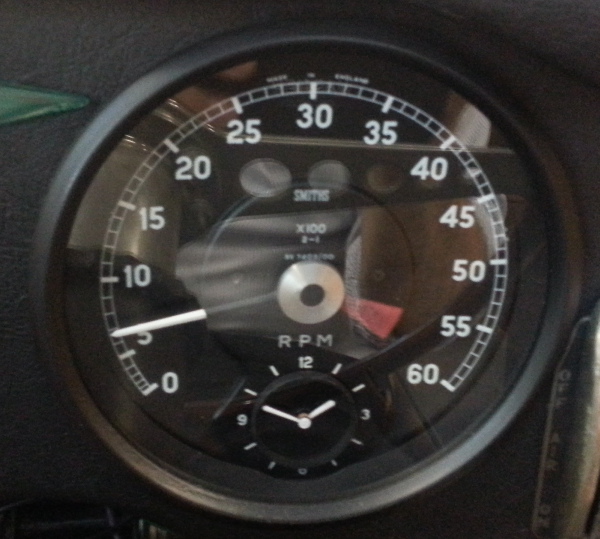
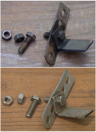
The larger picture shows the indicator switch — such as it was — on the steering column. It’s attached with a bracket setup that wraps around the outer tube of the column. The old switch clicked into place for left turns, but the right turns would not hold, making it necessary to hold the switch in place. The trouble was the nylon fitting that was cracked on the side that affected the right. We completely disassembled the switch and discovered some pretty badly burnt points and worn plastic (Bakelite?) housings. In short, the indicator switch is pretty much junk. It’ll be entirely replaced.

The steering column consists of two major parts: an outer tube and the shaft. The shaft is held in place by two bushes, one at the top of the tube and the other at the bottom. The bushes are available in felt or plastic. I went with the plastic versions, in spite of the fact that the originals were felt. The felt bushes are sandwiched by washers and held in place by a wire circlip that snaps into holes on the top and bottom sides of the outer tube. The plastic arrangement is much simpler, since the plastic ring simply snaps into place in the holes. (The holes for the upper bush are visible in the picture on the left.) The two bushes have unequal inner dimensions. The lower bush is smaller than the upper one, since the shaft tapers in stepwise fashion from top to bottom.

When we picked up the car, the steering column shaft was noticably shaky in the tube. This was because a previous owner didn’t bother to replace the felt bushes but instead rigged up a plastic arrangement. This “bush” was mounted centrally on the column (a great pivot, of course), fashioned from a plastic bottle cap, and affixed with electrical tape. In order to reduce drag, I suppose, the entire shaft was smeared with grease. It is actually amazing that the shaft didn’t bind firmly in the tube, because the electrical tape easily unravelled.

I took pictures of the plastic replacement bushes, but (alas) they are stuck on my digital camera. The dongle has disappeared from the household, and of course no one has any idea where it is. When it reappears (soon, I hope), I’ll post a photo of the bushes.

‘Til then….