Left floor installed (20 – 22 February 2003)
This actually went quite quickly, even though our logs say it took two days. The issue was amount of time spent on each of those days. I set up a fair amount of 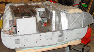 welding, and Aaron did the welding, for the most part. As I said in the last entry, the floors look like Real Headway Being Made, even though the preparation — essential as it is — consists of putzy little stuff. We push to make the putzy little stuff as painless to do as possible.
As with the right floor panel, we used a (non-standard) bolting strategy, with the bolts along the front end, the inside of the panel facing the transmission/engine space, along the cross member, and along the back of the panel. Size of bolts and attachment strategy for the left side was the same as for the right.
Symmetry is good.
The outside edge 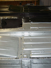 of the panel (along the seam of floor panel and outer sill) had a very natural fit. We basically just laid the panel on the car and welded. However, the central portion of the panel (behind the cross member where the right and left floor panels meet) seemed to bulge a bit. We will bolt that area in any case, and probably weld it as well. As I recall, the original floor panels had a separate panel attached in this area, which is the part that forms the “floor” of the drive shaft tunnel. I don’t know that this original panel was an original part, in any case. (I haven’t look at the notes or at the parts themselves, but this piece may actually have been something other than metal.) The pictures I have seen of this area don’t show a metal cover over the area. And yet, a sheet covering the area where the floor panels meet actually doesn’t sound like a bad idea.
I might just do it, since I’ve seen enough nasty rust form in that area.
The fitting of the entire floor means fitting the parts that straddle each floor panel, and this means the “rear floor stiffener” which I had fabricated earlier. As of 25 February, we had just fit this piece using clamps, and we haven’t welded or attached it to the floor yet. Here again we will be a bit out-of-the-ordinary, since I want to use 1/4 inch bolts to attach the stiffener. We’ll use eight bolts, four to each side. In between we’ll spot weld.
Left wheel well repaired
With the car flipped over, it was easy to get at the rust damage at the top portion of the left wheel well and the so-called “fillet” where the rear portion of the cockpit 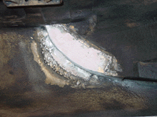 interior meets the lower edge of the convertible top. This area has been badly corroded, and crudely “fixed” with Bondo and wood strips (!). We had removed this blodged repair, and intended on doing some metal work. That we did, with two pieces of 20-gauge metal. The first piece was aligned with the curve of the upper portion of the left rear quarter panel, and the second piece (welded on top of the first piece from inside the wheel well) formed the fillet wall. As with other fixes, we ground off the welding excesses, and used Bondo to smooth the surface. We were actually less worried about how this fix looked, since it is in a place where you really need to want to look to see it at all. After the application of Rock Guard to the area, this fix won’t be easily visible. But trained eyes will see it, I guess. If they look for it….
I should say that cleaning the original rock guard from the inside of the wheel wells and the IRS corridor between them has been a real chore. I believe that the original coating remained, but a later owner must have applied some “rust-proofing” to some areas, especially where we found significant rust damage. Fortunately (or not), these gunky areas were removed in order to repair the rust. But residues of the goo remained in other areas, and just made a mess to clean off. An acetone-based solvent seemed to soften the coatings, but not entirely dissolve them. We were able to scrape off a good deal, and then the solvents took off the rest. Or, at least the solvents made it possible to smear it around a bit. For the record, the coatings were a yellowish color, though that might have been their age showing.
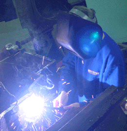 transmission bell housing. It’s not particularly clear what exactly required such invasive and destructive work to be done. I was thinking that perhaps there was simple laziness at the root of it. For typical adjustments, the E-type has adequate portholes going into the transmission area. But perhaps this was starter work? A clutch job (unlikely, I think)? We shall probably never know.
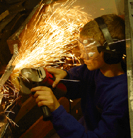 Anyway, I fashioned a replacement piece for the front engine/transmission housing wall out of 18-gauge steel, and I cut out the damaged piece from the transmission cowel. That piece we replaced with another piece of 18-gauge steel. Aaron did the welding and the grinding.
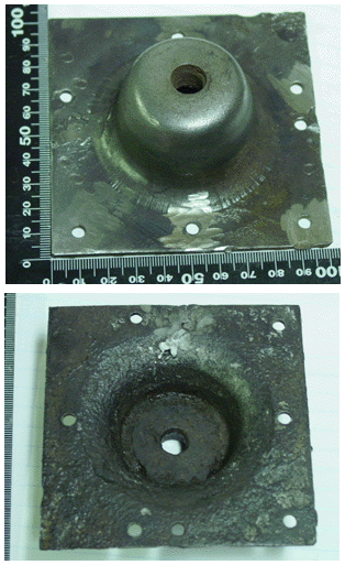 the existing cups and one of them was corroded beyond repair. I ordered a replacement for it. The other one still lingers in my mind as a repairable piece or as a replacement piece. We did go ahead and repair the cup that still has structural integrity, though questions remain because of the threading in the center of the coupling. They are not exactly well defined. I could, perhaps, go ahead and retap the threads with some success. At this point, we are going to wait until the new part arrives (sometimes after the Thanksgiving Holiday, I was told) and then we’ll make a decision about the replacement. I definitely do not want to install a restored part that will fail after a few thousand miles!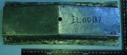
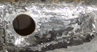 the paint from the inside of the trunk. The fix entailed cutting out the corrosion and the entire fuel filter cup hole, even though the rust damage was isolated to one side of the hole. I figured it would be easier to create an entire hole than it would be to try to fashion a piece and attach it flawlessly to the “good” metal of the original hole. Once again, this was a matter of exactly fashioning a replacement piece, welding tabs to the hole, and welding the new piece onto the tabs.