This one is for Derek, my eldest of sons, kind and level-headed. —Also more reasonable than I am, probably. It has been a great blessing to have the children Arlene and I have raised, and we both know that our lives together have been a matter of luck and work, however mixed. We count our blessings, and the first among all of them are our children.
It moves on its own, at last
I was talking with one of my colleagues at work, and he recalled when he started working with me — it seemed long ago, four or five years — and this old car was still in the garage. Actually, long in the garage, being putzed with and pampered and fixed and prodded. But it’s right on the edge of moving out to a new life on the road. Or at least that’s what I hope.
It seemed interminable, this long wait for the car to move. Here, too, there was an interruption, since my fix of the coolant leak was in fact no fix at all. But after Aaron returned from NASCAR Technical Institute in November and his tools started to pile up in the messy garage, there was in fact little choice but to get cracking on the last bits — the clutch hydraulics and the setting to rights of the brakes. Since Aaron came home, brake bleeding was not the chore it was before, but we discovered that the front brake master cylinder needed some fettling, since the play of the piston was not sufficient. I had a spacer for the master cylinder (from an old XJ or early S-type, I believe), and we installed it on the front master cylinder, which is fitted topmost on the pedal assembly. Works great now. Remember, this is due to the non-original Wilwood master cylinder conversion.
The clutch hydraulics were simple. And Aaron pushed a little by pushing the old car out into the elements so that he could fit his tool cabinets into the garage. I was not pleased that the car was under a tarp outside, but we got it done in part because I wanted to get the thing moving and back into the garage.
All was installed, and so coolant and oil went into the engine. It fired up great, and it moved on its own the forty-some feet into the garage (which by now had been cleaned). We ran the engine a few times thereafter, basically checking out the movement of coolant, the operation of the thermostat, the idle, and the like. It looked good.
I figured it was all downhill from there. It wasn’t. The coolant leak revisited the car, like some unwelcomed haunt.
Aaron called me one afternoon and told me that coolant was again in the oil, so the shade-tree mechanic “fix” wasn’t working. He had removed the oil pan enough to be able to locate the area of the leak, pressurized the cooling system, and discovered that the inlet from the water pump through the timing chain cover was leaking somewhere. A dribble of coolant was coming down the left side of the timing chain cover and into the oil pan. There was little to do but take the cover off.
It took only a few moments of looking at the inlets on the 3.8 and 4.2 liter timing chain covers to understand where things had gone awry.
Another difference between the 1963 3.8 liter and the 1979 4.2 liter XK engines
I’ve done some comparisons of the two engines that we’ve taken apart for this car: the differences of the cylinder heads and the blocks. I missed a rather important difference in the timing chain covers, though, and that was what came back to bite us. 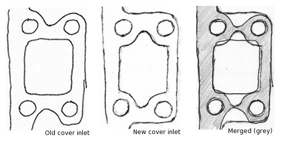 The 4.2 liter engine eventually had a better water pump installed and the passage through the cover into the block was slightly bigger and shaped to allow better flow of coolant. It was the difference of the inlets and the areas where the inlet passages were mated that made all the trouble.
Why not use the 4.2 liter engine cover? I didn’t have a water pump to fit. The XJ6 water pump I had would not clear the front of the engine bay, since it went forward beyond the “picture frame.” I couldn’t locate a new water pump either, since everywhere I looked, the water pumps were available only with core exchange or were “R&R” serviced.
A quick glance at the images that compare the 3.8 and 4.2 liter cover inlets shows the true source of the leakage problem. When you compare the two inlets 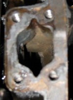 (note the grey area to show the overlap), you can see that the curved sections end up severely narrowing the “kiss” of the cover to the block. And in fact the shape of the coolant inlet on the 4.2 liter engine block is even more pronounced than the cover’s inlet. Although it’s a little fuzzy, the photograph of the block inlet has “points” rather than curves at the upper and lower edges. If you look carfully, you might be able to see the place where the old 3.8 timing change cover (mis)matched the block inlet. I would bet that the leakage we saw came from the lower edge of the inlet, and that it arose only well after we had run the engine for a while, making it possible for the low pressure hot water to push the RTV out of the way.
Now the question was what to do. Obviously, the option of fitting the 4.2 cover would have been best, and I even toyed with the option of arranging a remote electric water pump. The prospect of begging for a 4.2 water pump was wholly unappealling, but was an option (and in fact still is an option now). The last option was to alter the 3.8 cover so that it would at least provide a more ample mating surface to the 4.2 block, in effect following the squared outlines of the 4.2 inlet. This was the option that we chose. The real debate was how to go about making the alteration. The initial approach was to build up the surface by welding aluminum and then machine the surface flat. I was very near pulling the trigger on that option, but the very real possibility of warping or distorting the cover made me hesitate. We could well end up with an unusable part, and we were throwing ourselves on the mercy of welding shops that would make no guarantees. The alloy of the cover was also an issue, I suppose. Lord knows how close a match the built-up metal would need to be.
Of course, there wouldn’t have been a debate without another option, and that was J-B Weld, I’m afraid. Now, I know that the stuff is broadly ridiculed, but I 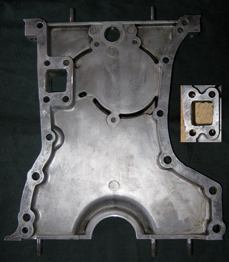 suspect that it’s also used more than people will admit. I’ve used it as an adhesive and filler on knobs and decorative parts of things. The bad reputation comes from people who use it idiotically, and I think that the J-B Weld marketing doesn’t help — engine blocks being “mended,” testmaments that the stuff is “better than baling wire” for farm implement repair, and the like. (As an aside, I have to hand it to the J-B Weld marketing people since they pitch their product to those who will actually buy the stuff — that is, the people who wander around Lowes and farm supply stores. They’re not pitching their product to machinists or welders.)
The stuff is tough, and J-B Weld claims a tensile strength of 3960 psi, adhesion of 1800 psi, flex strength of 7320 psi, tensile lap shear of 1040 psi, and shrinkage of 0.0%. It can handle temperatures up to about 600° F. These measures are of course less than aluminum, but they’re certainly within the range required for an area of little stress and reasonably low temperatures like where we needed to make changes. My main concern — and the crux of the debate — was adhesion. A J-B Weld alteration might hold up, but if a failure occurred it would probably be when a chunk would let loose from the filled area. A chunk falling into the oil pan or timing chain would be quite enough to ruin an engine in no time. The question of using J-B Weld has to do with where one draws the line between good use and idiocy. The application on the timing chain cover would not be stress bearing, though 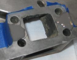 the area would experience temperature changes. As is the case with most adhesives (all of them?), surface preparation is the key to good adhesion.
No surprise here, I guess, about which way we went. The probability of immediate damage from welding and hypothetical (and, I think, remotely likely) failure of a J-B Weld application tipped the decision in favor of J-B Weld. Since the timing chain cover was out and easily cleaned, I went at it with all sorts of cleaners. I roughed up the area to be covered with coarse sandpaper and then scored the surface with a sharp probe tip. A final cleanup of residues and oil was all it took before I set up a dam made of masking tape. Then it was a matter of putting the J-B Weld into place. Twenty-four hours later, I brought the epoxy bumps down flush with the cover, and it was done.
By now, we have removed the cylinder head twice in search of coolant leaks. The oil pan was dropped once. The timing chain cover came off once. I sure hope this is the final chapter on this issue. It is interesting (at least to me) to reflect on the process of fixing up the old car. It is a mixture of physical grunt work, much cussing, posing hypotheses, scratching them off or confirming them with observation or test. This episode with coolant leakage was in fact as much an intellectual exercise as it was mechanical work on the car. The fact that it occurred shows the importance of documentation and keen observation, since had I just looked carefully at the differences in timing chain covers the issue would have been resolved the first time. Much oil and antifreeze would have been spared. And, more importantly, I’d be doing something more close to the finish line for this car.
On my birthday, by the way, I got a convertible top frame that David Boger located. It needs a little work, but I think the pieces I have at hand might do the trick of mending. I can hardly wait until I can put that on, toss in some seats, and drive the car around!
 body panel, but the bottom portion did not. At the bottom edge, the metal was sticking out about 2 centimeters — a significant bulge to finesse with Bondo. I actually thought about just leaving well enough alone and using Bondo to cover the lower portion, and yet that seemed a bit sloppy. I ended up cutting off the portion of the metal that wasn’t tight and fashioning a plate to refit into the hole. I ground off the messy weld-metal, and refit the portion. It fit nicely. I then welded the two pieces together along the seam, and then ground o
 ff the excess weld. Bondo flattened it up well enough. Since the hole was inset the thickness of the sheet metal inside the trunk area, I sanded and cleaned up the area around the hole and bondoed the indent so that it is flat. Of course, the fix lacks two of the creases that are normally found on this body panel, but this fix was good enough. It is strong, and since it is covered by upholstery, it will also be invisible.
 windshield. These could not bear the weight of the body, and we made sure that theynever touched the floor as we lifted and turned the body over. This was mainly a matter of placing the rear (the so-called “boot”) of the body on a pad on the floor, then removing the support from the front. Once the entire body rested on the floor we literally rolled the body onto its side. Then after having placed the support for the front where it could accept the body and support it, we lifted the front part of the body up, leaning a portion of the body weight onto the rear section. We settled the front onto the frame support, lifted the rear section and put the supports for the rear into place.
 I was wrong, it turned out, since the bottom of the tranny tunnel hadn’t been well enough protected from moisture. The tunnel has a bit of an indentation on the driver’s side, where the emergency brake lever is situated. This piece contains the hinge for the lever, an electrical switch sensor that lights up the emergency brake light, and the cable housing leading to the rear brakes that are engaged by the emergency brake. (Incidently, the E-Type has a separate set of brake pads that are engaged by the emergency brake.) The bottom of the housing for the brake mechanicals and switch was completely absent — eaten away by moisture seeping and spraying from the road, presumably.
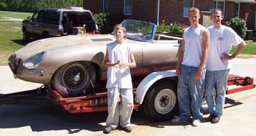
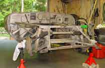 the D-type, which won the Le Mans in the late fifties. That car was of tube construction. The E-type we are familiar with is partially tube construction (the area in front of the “bulkhead” which begins in front of the dash) and partially structural sheet metal construction (everything else behind the dash). This is an enormously strong construct.
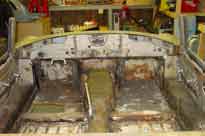 The outer sills got rusty, so they were replaced. The trouble was that the areas behind the outer sills and internal to the sill structure overall were (probably) ignored. Because the inner sills lay behind coverings of the interior or were less easily accessible, they were ignored. In short, the trouble is there, but it’s harder to see and harder to repair. Deterioration of the inner sills became apparent after we removed the interior trim — the carpeting (such as it was) and the felt padding. Rust damage was especially bad in the front left foot well inner sill. It’s not clear in my mind whether the entire inner sill on the left side will need replacing. I am now thinking that it will not, though repair is required. The final verdict will be clear after sandblasting.
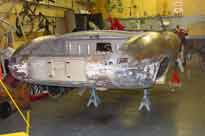 were rusted through and repaired with bondo. We’ll fashion a metal replacement, of course. Other rust damage in the rear was related to the deterioration of the sill: the rear quarter panel on both sides were bondo-ed — perhaps the most shameful of the early repairs, since the bondo hides a multitude of sins. The areas immediately behind that bondo were in bad need to replacement. We will tear that bondo out (as we will do with all the bondo) and probably open up the rear quarter panel in that section. This will allow us to replace the internal structure.
 cutter. We had trouble loosening the top two timing chain sprockets, but we circumvented that by removing the cam shafts. The cam shafts look quite good, and their bearings look practically new. The valves show some normal wear and tear, but none is compromised with a blow hole. Pistons are blackened, but everything moves nicely in the cylinders. We haven’t removed the oil pan to look at the connecting rods and the crank shaft.
 could wrestle enough room to remove it. (This was one of two big black spiders we ran into.) It dropped like a charm. Read the shop manual instructions carefully to get the details on easy removal.