Category Archives: Braking system

January 2009 – Setback and brakes

I have to apologize to the many good folks who have contacted me wondering where the restoration stands. It has indeed been a long time since I have updated the web site, though I have intended to do the work often. A mixture of other things to do and some technical difficulties (a new computer and lost digital camera, mainly) conspired to keep this year (!) of work on the car more or less secret. But things have indeed been progressing. It is likely (and a little weird) that this entry will be the only one in the sixth year of restoration.

Coolant leakage

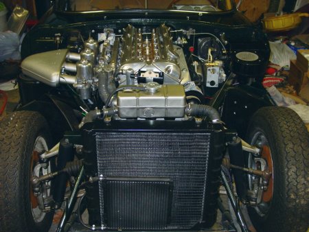
It has been some time since the triumphant first start back in September 2008, but the time was not without events or work on the car. It turned out that somehow coolant leaked into the oil, a fact that I discovered to my horror when the oil cooler circuit broke and I saw oil squirt out with the color of well-creamed coffee. It looked luscious and rich, and it meant 
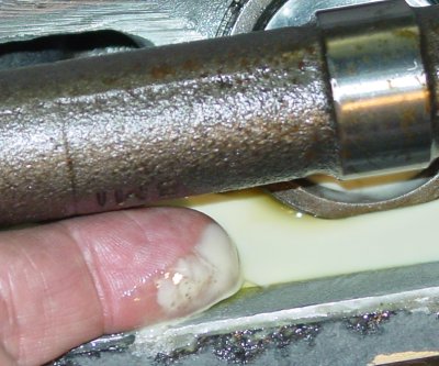
nothing but trouble. The first thing that I did — after cleaning up the considerable mess — was remove the oil cooler. I suspect that the lines were insufficient for the pressure, and they were going to cause trouble anyway.

But the cooler setup was not the cause of the leak inside, and so the weeks and months that followed meant considerable speculation and telephone calling. I was skeptical that the issue was a head gasket — the thing was brand new, after all — but the fact was that there had been occasion enough for something catastophic inside. The mistaken wiring caused a good deal of explosion (when the effect wasn’t just straightforward flamethrowing). And there probably was high oil pressure due to the craptastic oil cooler. So, I took off the head after many weeks of trying to avoid the job. The gasket was in fine shape, and I replaced it nonetheless. So much for premature head gasket failure.

How about the truth of the head and the block’s deck? The head was newly reconditioned, but the block was not. Both looked fine when tested with a straightedge.

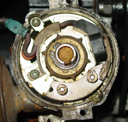
Then I remembered, very vaguely, seeing a silicone worm around the timing chain cover. A search of my photographs came up with nothing, an obvious failure of documentation at the tear-down.

So, the water pump came off, and I probed at the interface of the timing chain cover and the block. I did find a point where the probe was “sticky” — as though it was poking into a very small hole. This hole pretty much corresponded with my memory of the worm. The fault must be in the timing chain cover, since I have a new block on which I fitted the original timing chain cover. I was of course presented with a situation of having to tear off the head yet again to remove the timing chain cover, or I could do what a previous owner had done. I chose to recreate the silicone worm. Next time the engine comes out I’ll be better about it.

I’ve not yet loaded up the car with fresh oil and new coolant. Who knows, I might be removing the head again anyway.

Front brake calipers and master cylinders

Assuming that the engine goes, I have to worry how to stop the rolling car. My initial plan was to recondition the original Dunlop master cylinders and front caliper setup (the original rear calipers are in place already). I had already cleaned up the originals, and I’d even plated the front calipers in anticipation of having the cylinders redone and new pistons installed. I was intrigued by the Volvo 
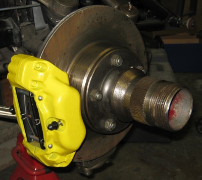
caliper upgrade, even though it went a bit against my desire to keep things pretty standard. The more I looked at it, though, the more it made sense to use the Volvo system. There is plenty of evidence that the upgrade works, there are some rather obvious advantages to it, and there is plenty of instruction on line.

“Sin boldly,” Martin Luther said, assuming that sin was inevitable anyway. So I sinned against the spirit of authenticity and adopted the Volvo brake calipers. I’ve done it boldly by painting the transgressions yellow. These calipers won’t hide, I’m afraid. But I do think they’ll stop better than the originals. The surface area of the pads and the pressure from the dual pistons will surely outmeasure the originals. It isn’t really all that bad, either, since these Volvo brakes were made by Girling, and Girlings were originally installed on many of our old E-types (just not these Girlings.)

Why yellow? Well, I’d seen a Porsche with yellow calipers and I liked it, and I do think the color makes no apologies for my “error.” I might be accused of being unrepentant!

I got “loaded” calipers — pads, retaining pins, everything — and they cost about $120 (USD). There is a bit of fuddling that is required and you have to make a decision about whether to “split” the caliper halves or not. I chose to split them and use the drill-between-the-pistons approach to unify the brake fluid input. There was no forcing required, and the caliper halves came apart quite easily. I don’t really understand the worry that some people have about splitting the calipers. As David Kerr puts it in his step-by-step instructions: “I think a lot written about brakes is folklore, people will not touch brakes simply because they are afraid of the consequences. The faces of the caliper are machined flat, as long as the matched pair are reunited, there really shouldn’t be a problem.”

There isn’t much reason to present yet another step-by-step instruction set for the Volvo caliper conversion, since this road has been well travelled before. See the following:

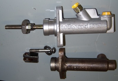
  • “XKE Brake Upgrade using Volvo Calipers” by Brian Ternamian [PDF] uses a “T” to distribute brake fluid to the two fluid inputs. No splitting of the calipers is necessary.
  • “XKE Brake Upgrade using Volvo Calipers and the Drilled Split-caliper Single-line Method” by David Kerr [PDF] uses the method specified in the title.
  • Modifying Volvo Brake Calipers” by an anonymous Nova Scotian presents another method, though I worried a little about narrowing the pad retaining pins.

In short, there is plenty to read and learn before even ordering a part.

The Dunlop master cylinders were pretty rough when we pulled them off the car. One had already been resleeved and the sleeves were in pretty decent shape, but they were rusted and ugly. The rubber parts needed a refresh, of course. Over the years, I’ve read about troubles with these cylinders leaking, with the rubber rebuild parts being suspect of either premature deterioration or being ill fitting to begin with. In short, I wasn’t particularly wild about putting the old ones on even after a careful rebuild. I moved from an initial plan of rebuilding on my own to sending them out for a complete and professional redo. 
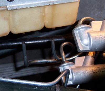
So, I did what everybody does. I googled.

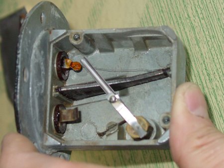
There wasn’t a straight swap for the Dunlop master cylinders, but I ran into some decent specification for a Wilwood master cylinder that could be “drop-in” along the lines of the Volvo calipers. The lines wouldn’t work without some fiddling. The mount into the pedal box required a minor swipe or two of a grinding wheel to open up the hole to accept the mouth of the cylinder. The “plunger” that attaches to the pedal assembly also required a fair amount of work — basically, the plunger for the adjustable fork had to be tapped further, and the other plunger from the original Dunlop needed to be used on the other master. This meant removing the circlip and making the swap. I bought two of the Wilwood 3/4 inch bore “compact remote” aluminum master cylinders (P/N 260-6089) from JEGS (http://jegs.com).

The Wilwoods are aluminum, so they’re lighter than the Dunlops and a bit stouter. The orientations of the inlet and outlet are also different. Where the Dunlop has the inlet coming straight out the back, the Wilwood orients the inlet vertically. The outlet for the Wilwood is shifted to point 45° forward. The threading is the same, however, so you can reuse fittings. Also, the Dunlop master cylinders orient the outlet vertically once they’re installed in the pedal box; the Wilwoods point the inlet and outlet 45° towards the center of the car. It’s worth noting that the Wilwood master cylinders are very similar to the standard-issue Girling clutch master cylinder, with the exception that the Girling is a bit shorter.

This tilt of the inlet and outlet makes for some interesting line-bending maneuvers. I decided to send the brake lines low — obviously, the line heading aft had to go low in any case, but the line heading forward could have been kept above the master cylinders. Sending it below, I think, allows more flexibility and provides some measure of vibration absorption. This meant that all the lines — inlets and outlets — had a bit of crowding beneath the master cylinders. Accommodating the inlet lines from the brake fluid reservoirs turned the lines into a well tied knot, it seemed at times. But they finally fell into place.

So, with the master cylinders in place and the Volvo plan, what’s left? Due to another unfortunate event, my air compressor needed fixing, and so the installation of the the left-side caliper was stopped. I still have to run the lines for the clutch hydraulics, too. But when those are done, the thing can run down a back road, even though it’ll be loud without an exhaust system. I told Neil Purves that they plan was to get the old car moving before the summer ended. It will run up the gravel road behind my place up to “Froggy Hollow” and back.

I just need to cordon off the time to get the last bits in place.

Buck for rear windshield

In the earlier part of the year, I finished making a buck for making a Plexiglas rear windshield for my hardtop. I haven’t tried creating a windshield yet, but Ray Livingston suggested that I use an infrared heater and heat slowly. My impatience with the process has made my initial experiments little bubbly disasters. I suppose I’ll give it a go this fall. I just have to make a wooden support for my heater. That’s about as fancy as I’ll get with the windshield. If this doesn’t work, I’m off to the store to buy one. Enough fiddling.

I’ll try to be better about updating, though I know I’ve said that before. Thanks to all of you for your emails over the past several months.

July 2008 – Miscellaneous since February

What we’ve done since February (!) 2008

This one is for Dan.

Just under a year ago, I said I was looking for a double-groove crankshaft pulley. I published a humorous email exchange at the time, and I had resolved to get a new pulley from Classic Jaguar. Funny how time flies — I had no idea it’s been a year since that time until I fished around on my website for that link. People ask me how the car is coming, and I think how leisurely the pace has been, punctuated by flurries of great activity. I have taken Mike Moore’s advice, given a few years ago on the Jag-Lover’s forum, to do something every day, even if it only amounts to cleaning tools. Sometimes, I’ll have to admit, I have been content to gaze upon the car — as if looking constituted work.

At any rate, I did get my pulley from Classic Jaguar, but I got a used part — my preference actually. And Dan Mooney was gracious, since I didn’t need the accessory pulley and bolts that he offered on his used parts listings. Dan has always been gracious and supportive through the course of this restoration, and I have used the Classic Jaguar website a lot over the years to watch the pros at work. I like to think I’ve been able to take cues, at least, from what happens in the CJ workshops, but I don’t think my toolsets quite match. Neither does my talent, alas.

I went ahead a few weeks later to pick up a used low brake fluid level switch from CJ’s used parts collection. One of the two that came with the car broken too badly to repair; the other seems workable until I get around to replacing it or can figure out how to mend it. That is a challenge since the things were put together in a way that defies taking apart, and I ended up breaking both of them utterly when I was struggling to get the aluminum canister off. See the used replacement’s innards in the picture below.

Aaron has been involved with this restoration over all of the years, and he leaves to NASCAR Technical Institute in Mooresville, North Carolina, at the end of August. He told me that he wanted to get the engine running before he left, but it looks as though that’s probably not going to happen. We have gotten the major pieces in place, and in fact we have turned the engine over for a period to see the oil pressure pop up. (It went to 60 pounds in very little time, I’m happy to report.) Getting the ignition system straight has been a little bit of a challenge, mainly because I didn’t take the time to actually look at the distributor insides. I was expecting to hook the thing up like the original 3.8 liter engine, but the new engine has an electronic ignition, so the setup is significantly different at least at the distributor. (See the pictures below for comparisons of the original distributor and the newer one.)

The fuel pump is in place, but I haven’t connected the run of wire from the “rear” harness to the cockpit harness yet. (Remember, I modularized the wiring harnesses a bit more than they already were.) The fuel tank filler hose is in place, too. I had to buy one of those little pieces of rubber from a Jaguar vendor, because I couldn’t find a hose with the right inner dimension. Not even McMaster-Carr had something suitable. But I did some searching after I got the hose and could use the printed numbers on the rubber. Goodyear offers “Fuel Fill Hose SAE 30R6” in various inner dimensions. I believe an inner dimension of 2 1/4 inches would do the trick.

Various pictures collected over the months

The fuel level sensor. Essentially, it’s a rheostat. (Er, maybe a potentiometer, but I think not. The thing has two, not three, leads.) The whole thing is quite delicate, so if you go the route of cleaning it, be very careful. The brass float that dangles into the fuel drives the blade. There are two “switches” so to speak — one that signals the variable level (the rheostat) and the other that is on-off that signals low fuel. The lid that’s removed in this photograph plays a role in completing the circuits, too. When I opened this little box up, it was quite encrusted. Cleaned up pretty well, though.

Looking down the XJ6 exhaust manifolds. I used the XJ6 manifolds that came with the engine I got from David Boger. Rather than heading straight down, the lower pipe slants backwards just slightly, and the manifold include a bolt-like bung hole plug. That plug makes it much too tight a fit against the left subframe, so I cut off the plug. The picture shows the front exhaust with plug and the rear exhaust with the plug cut off.I like the XJ6 manifolds for another reason: they include a heat shield setup that would seem to reflect heat downward. With all of the work on the paint, I really don’t want to have heat damage around the left louvres as I’ve heard some people have seen. Of course, the change in design means that the exhaust will have to be specially crafted, at least from the base of the manifolds to the front of the muffler section. I don’t think that will be too much of a challenge, though.

The engine compartment. Yes, please don’t pay attention to the mess. One of the thing I could do (but, apparently don’t) is take time to clean up the garage. It is shared, for the time being, with son Aaron, who also leaves his junk around. Working on my car includes quite frequently asking Aaron where tools are. But, aside from that, the engine compartment is coming together nicely, creating a sight that offsets some of the garbage in the background. Notably absent are the brake and clutch hydraulic fluid reservoirs and much else on that side of the engine. Since the time this photograph was taken (early July 2008), there has been some additional progress. A battery has been fitted, the heater fan assembly has been more firmly put in place, and a new starter solenoid (which still hasn’t worked right) is set up.You can see the oil cooler setup quite plainly, of course.

The rusty brake rotors need calipers fitted — and to be used — to get them clear of the red iron oxide. That, too, will come.

Lucas 22D distributor with condenser and points. This is the inside of the distributor that came with the 3.8 liter engine. It’s a Lucas 22D (note the marks) and it’s what I’m familiar with — mechanical and old fashioned with points and a condenser. I suppose I could use this one, as Glen Jarboe has on his 4.2 after he went through his engine rebuild. I’ll put this one aside, though, in favor of the distributor that came with the 4.2 replacement engine (below). If that one needs replacement, I might go with a Pertronix.

Lucas AB14 distributor with sensor. This distributor came with the engine I got from David Boger. People on the Jag-Lovers XJ6 forum seemed to think that this distributor is the Lucas AB14. It’s got a “CEI” (Something Electronic Ignition, probably) that has a sensor instead of the more mechanical approach that I’m familiar with. Peter Crespin, who knows a lot more than I do about these things, explained that the star-shaped center portion is a “normal six-point reluctor for the Hall effect pick-up coil at the side of the base plate.” This setup requires an amplifier, and David will be sending one to me. If the old electronic parts don’t pan out, I could install the mechanical 22D or put in a new Pertronix. My thanks go to Frank Anderson, Al McLean, Peter Crespin, David Boger and the Jag Lovers’ XJ6 forum.

A handy mechanical oil pressure gauge under the bonnet. I’m not terribly impressed with the track record of the electronic oil pressure gauge. People seem to think that they’re maybe accurate to within 25% (and I believe that might be half in jest). With the two oil pressure sensor possibilities on the 4.2 liter engine I got, I went ahead and installed a mechanical gauge next to the windshield washer bottle and above the fuel filter bowl. The copper tubing goes to where the on/off pressure sensor used to be. I believe that the XJ6 had an oil pressure sensor there that was attached to an engine cutoff. The electronic sensor for the gauge was broken on this engine, and so I might attach the sensor from the 3.8 liter engine. It’s old, but it might work.Then, again, I might just stick a non-standard mechanical gauge in the cockpit. Lucas ones are available, I believe, though they display a different range of oil pressure than the electronic gauges do. Having an oil pressure gauge in the engine area is really nice. I’m considering installing a tachometer nearby, too. I believe they come in the two-inch form factor

Insides of the brake fluid level switch. Both of my brake fluid level switches ended up being less than desirable. Both of them cracked when I tried to remove the aluminum canister that protects the cork float. One of them is more-or-less intact and still sits atop a fluid bottle, waiting until I replace it. The other broke into small pieces, and so I replaced it with a used part from Classic Jaguar. The replacement was really nice, and when I removed the aluminum canister, the top part came off. I took advantage of the inadvertent disassembly to clean and photograph it.The thing is dead simple. Simple enough that you’d think replacements would be cheaper. I just wish there was a way to replace the top cover and the canister without having to replace the whole part. The inset photo shows where the two contacts are hit by the metal disk that’s attached to the rod and float. One thing that might help others trying to replace a besotted cork: There is a hole near the top of the canister that is slightly pressed into the plastic of the assembly. If you take a knife and remove part of the aluminum that’s pressed into the hole, you might find removing the canister easier. It worked for me.

January-May 2005 – IRS rebuild

IRS rebuild

I had read the an IRS rebuild is actually straightforward and not too challenging. I agree. I also have a new measure for how long it takes: in winter it takes as long as a thumbnail to come back in; in summer, probably considerably less. I know the thumbnail timeframe because I managed to pinch my right thumb while removing the differential on the first day of working on the IRS. Now, with the IRS back in place, my thumbnail is just about back to normal, having fallen off and regrown since January.

I had expected the refitting of the several washers, bearings, and seals on the wishbone assemblies to have been the hardest of the tasks. (I didn’t take on the differential, except to do a visual inspection.) It turned out that I’d have to rank redoing the “safety” wires to the drilled bolts as the most challenging part of the job. I spent more time figuring out how to cram my fingers into the tightest places. I still wonder how the work was done on the assembly line, though I believe that the least accessible bolts were finally fitted with lock washers in lieu of the safety wire.

With some solid work, I think you could take on an IRS in a full week. My rebuild took a little longer because I was working in winter, and I ordered parts over a period of time. Also, I mistook the number of parts I needed, making me halt progress while waiting for replacements.

Removal of the innards of the IRS is quite easy, if you follow the shop manual. I recruited my boys to help lift the entire assembly on top of a low shop table (and that was shortly before I managed to crush my thumbnail). After the components were apart, the weight no longer mattered, since every piece is manageable — though the differential itself is a heavy chunk of metal.

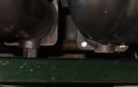
Rotor alteration. I ordered new brake rotors in March, and those presented me with the first challenge. Holes drilled through the rotors provide access to bolts that affix the brake caliper assembly to the differential case. The replacement rotors had slightly different hole placement than the ones that were fitted to the IRS. (I am very confident that those old rotors had already been replaced once already, so they were not original.) The new rotors had holes too far from the center, making it impossible to slip a socket through to tighten or loosen the bolts behind the rotor.

The fix was to shave about two millimeters off the semicircle toward the center of the rotor. This made the hole slightly larger in one direction. I did this to both holes equally, so that even this slight amount of weight difference on each side of the rotor wouldn’t cause a problem with balance.

If you check out the illustrations in the shop manual, it looks like the new rotors have more original placement and size of bolt access holes, since the shop manual shows the holes extending across the angled gradation from the bolt-fitting plane to the plane of the rotor-brake pad face. The rotors that were on the IRS had smaller holes placed on the plane for the bolts. See the illustrations below to see the difference.

The old rotors were the same thickness as the new, but they were quite rusty. I am tempted to bring them in to have them turned, just to see how much of the rotor had been consumed. There is a chance that they still could be used, though with the trouble of getting to them it would be silly to put old parts into the IRS.

Brake plating and renewal. Like the front brake assemblies, the rear brake assemblies needed plating. I did the nickel plating on my own, as I did with the front assemblies. I was a bit surprised by the size of the brake pistons, which were much smaller than I was expecting. I noticed that Classic Jaguar often uses the front brake slave cylinders on the rear, and I had mistakenly thought this was for some reason for wear or the like. But it turns out that using the front cylinders for the back amounts to an enhancement. (I looked at Haddock’s Jaguar E-type 6 & 12 Cylinder Restoration Guide later, only to see the difference in cylinder size documented.)

I was also expecting to see Dunlop castings, as appear on the shop manual drawings. Instead, I found what might be Girlings, at least that’s what I’ve assumed since the center of the cylinder casting shows a “G” with a centrally placed hand grasping the letter’s left edge (see the photos). I believe that Girling eventually came to be a supplier for brakes, but I thought this switch took place later in E-type history. From what I can glean from the web, it looks like Lucas and Girling began to co-manufacture in the 1950s or 1960s. I know that today they are considered one and the same, though it’s odd that there is no website for the company — at least Google doesn’t seem to report where it is. Perhaps they have consistent electrical problems and can’t keep their web server running. Perhaps Lucas-Girling no longer exists, except as a name.

As a side note, I had prepared for equal sized cylinders in my purchase of cylinder seal kits — so I had two kits well suited for the front brakes. The trouble was that the rear brake cylinders are actually quite a bit smaller than the fronts. I bought a kit for the rear brakes from Terry’s Jaguar Parts for more money than I spent on both of the front kits.

Popping the brake pistons out is a matter of firing up the air compressor and shooting air into the cylinder. Be sure to keep the piston covered, since it will really pop out. The cylinders and the pistons were in good shape, and the rubber seals and boots (manufactured in Australia, by the way) showed no signs of wear or cracking. This was interesting, since the rotors showed wear, but they had very nearly the same thickness as the new ones, something I attributed to the expansion that comes with rust. We replaced the seals and boots with new, of course.

The hand brake setup has a separate set of calipers and pads, and these fit on top of the regular brake caliper assembly. These were a bit of a challenge to bring back into shape. I sandblasted the setup, which was quite rusty, and then I waxed the metal in hopes that it would be protected from corrosion. I later decided that paint would be more protection, and so I cleaned them all up again and painted. They look good, and I don’t think they will suffer from heat, since they shouldn’t do much other than hold the car in a parking place or at a standstill. Given the function of the handbrake pads, I didn’t expect much, if any, wear. Sure enough, there was none. I really didn’t need to replace them, though new ones went in.

I bent and appropriately flared new brake line. It is easy to do good double flares and bubble flares with the right tools. I really don’t know why people buy prebent brake line. New fittings went on, too, and those I had to cannibalize from other brake lines I bought just for the fittings. There must be an easier (and cheaper) way to get those things!

Differential. There’s not much to report on the differential. We opened it up to inspect the gears. We checked for any lateral movement or looseness. Everything looked good and felt smooth and tight. The red-brown paint on the inside of the differential was unmolested, but on the outside it had seen the grit of the years. The consensus on this red paint seems to rest on a brand call “Glyptal” which is a very low porosity enamel that is used to seal inside machinery. It’s used to seal up passages inside of engine blocks, and it’s used by Classic Jaguar in their engine rebuilds, I believe. It is currently available from specialists. (Though I’ve never found it in a auto part store of a paint shop around here, I think I’ve seen it in the Eastwood catalogue for about $40/quart). It’s been speculated that Jaguar dippedthe differential cases in the stuff, though I think that’s probably not the case. Whatever the process, the case and many of its innards are coated with the stuff.

I used a Rustoleum recipe for the exterior of the differential case. It’s a 1:1 mix of Rustoleum “Rusty Metal” primer and Red. The color matches exactly what I was able to find under the grime, and the coating is tough. I didn’t redo any of the interior of the case or its contents. I think Mike Moore, a restorer in the San Francisco Bay Area, gave me the recipe.

One thing we did notice when we drained the differential was how horrible the oil smelled. It was truly awful, and I think the odor might have had something to do with the leather seals in the differential. I suppose this would be a puzzle for an organic chemist to ponder. Also, we ran into what might be some Whitworth threads on certain bolts going into the differential. Certainly they were at least among the few “NC” threads (the course threads) on the vehicle, but they seemed to have a bit of a different angular pitch on the threads. I didn’t tarry long enough to research the matter.

We didn’t replace the differential seals, though the fiber seal for the case access cover was replaced since we destroyed it when we removed the cover.

IRS housing (or “cage”). One of the nice design elements of the IRS is that the entire assembly fits inside a housing that is easily removed intact from the body. It’s really just a matter of supporting the IRS underneath with a hydralic jack, removing a few bolts and detaching a brake line hose. Then, with the body supported, you drop the IRS with the jack and roll it out. The disassembly is a matter of removing the pieces from the housing.

After the wishbones, half-shafts, hubs, coils/shocks, and the differential were out, we cleaned up the housing and painted it with epoxy black paint. I know many people go ahead and use a powder coat on the IRS (which was perhaps the original finish?), but I didn’t go that route. The epoxy is very tough stuff, and I think it’ll do quite nicely, especially since this car isn’t going to see any moisture or tough wear while I own it.

Various notes. Bolt safety wire was a pain to install. I used 19-gauge stainless steel wire, and I didn’t bother to get a wire twisting tool. It seemed to me that the number of bolts I’d have to secure with wire wasn’t enormous, and besides that, many of them were very inaccessible. The safety wire was eventually abandoned and lock washers were used instead on the bolts that are accessible through the holes on the brake rotors. These are very nearly impossible to reach, and I can’t imagine how a production automobile could have used this tactic for securing bolts. (Of course, the run for the E-type was at one time only supposed to have been long enough to qualify the car for Le Mans — 500 copies.)

The wire twisting in the picture was comparatively easy to get to. Twisting it was another matter, as you can see by the less than perfect spiral. This bolt attaches the brake caliper to the differential and its safety wire goes through the other drilled bolt seen in the picture. The bolts that secure the differential to the IRS cage also use safety wire, and because it’s so accessible, it’s easy to do a nice job. That safety wire, I believe, has a certain ornamental value, too!

If you ever take a look at the “exploded” drawing of the IRS, the number of spaces, seals, washers, and such on the wishbone arms is quite formidable. I found out that the drawing is actually significantly more complicated than the reality, since the parts interlock predictably. I did wonder how to get the parts back into the right configuration and slipped into place before inserting the fulcrum shaft. I used multipurpose grease as a glue, and it worked very well. The IRS case with the differential and the yokes for the fulcrum shaft in place make for an exact fit. The wishbones with the various washers and seals just fit. I line things up and shove them into place. The last bit of adjustment was easy to do with a rubber mallet.

I had a bit of a time getting the last nuts off of all of the shafts — there are fulcrum shaft at each end of the wishbone and the shock absorbers are affixed to the wishbones with a similar shaft. Removing the shafts was easy, since you needed only to loosen one of the nuts, but getting the second nut off was significantly harder. After all, the nut that stayed on was more likely to be fusedon. I ended up soaking the shafts in kerosene, and then I used the air impact wrench to get the last nut off. All the threads were retapped and fitted with new bolts.

My shock absorbers (aka “dampers”) had waited some time in the parts bin — probably over a year — before they found their way into place. I bought Boge shocks, which are supposed to be suitable replacements for stock. The coils were in good shape, all with the correct height unloaded. I brought the old shocks and the coils to a shop to have them parted, checked and painted to coils, and then had the new shock fitted. (The bill amounted to $50, which seemed a little rich to me, since the job total took all of maybe fifteen minutes.)

The other work I had to have done in a (different) shop was pressing the big and little radius arm bushings in. I was able to remove them, but the big bushing especially requires some heavy pressing. After the IRS was in place, I installed the radius arms to the radius arm mounting cups, using plenty of copper paste to prevent the parts from seizing together.

So, two pictures to show the before …

… and after one more time.

November/December 2004 – Master brake/clutch cylinders and pedal assembly

Master brake/clutch cylinders and pedal assembly

I will remove suspense: two of the three master cylinders are all toast, victims of corrosion. The rest of the assembly is in pretty decent shape — nothing that a little paint remover, sanding, wire-brushing, and painting can’t take care of.

The master cylinders were a bit of a blow, though. Since they needed replacement, I wondered if I should just upgrade the brakes entirely to the 4.2 setup, since it was apparently more reliable and responsive. I decided not to upgrade; we’ll keep this one more or less as it rolled off the line.

I went ahead and ordered a clutch master cylinder as soon as I took the old one apart enough to see the mess it was inside. I ordered it from Terry’s Jaguar and it arrived a couple of days later, in fact much sooner than I had expected. It is very nearly identical to the original. I decided to take a look at the other master cylinders for the brakes before ordering replacements. One has already been resleeved in brass, and it was bright and shiny without a score mark. The plunger and various innards need attention, though. The other one seemed never to have been touched and was much worse off. Although much of the inside of the cylinder was clean, there were score marks concentrated in one area. It needs either replacement or resleeving. I emailed Terry’s Jaguar to see if they do resleeving and to see whether the metal internals are included in the master cylinder kits. Jerome replied that they don’t resleeve and the kits include only the rubber seals and the “dust cover.” So, at this point, I think I can use a master cylinder rebuild kit for the good, already resleeved master cylinder. I will simply cannabalize the best metal internals from the two cylinders. I’ll probably go with a new master cylinder for the other.

The pedal assembly itself consists of an aluminum housing that holds both the brake and the clutch pedals, and the housing also accepts the clutch master cylinder as well. A bent steel attachment sits next to the aluminum housing and serves to encase the brake pedal linkages (which are quite complex) and hold the twin brake master cylinders. The steel attachment is painted with “hammered” grey paint. Adjacent to the firewall and attached to the aluminum housing is a plate that holds the Dunlop vacuum brake assist bellows. This bellows set up was fairly short-lived in the history of the E-type, since it barely survived the 3.8 liter engine version of the car. The bellows themselves were manufactured by Dunlop, and the whole arrangement has been characterized as somewhat unconventional. But I have to admit that it seems pretty straight-forward, even though the 4.2 setup (from Lockheed, I think) is said to have provided about 40% better assistance with braking. The bellows system does appear not to be as scrupulously backed up and redundant as the 4.2 brakes. I considered upgrading to the newer system, which was carried over through the remaining history of the E-type, more or less intact, if I recall right. But I decided the pedal and braking installation was too visible to replace. I’d look at it and think it was too much of a compromise from the old 3.8 Series I.

I put the clutch/brake pedal assembly into place just for the sake of taking a picture. I figured that the work that was still to come would be easier at the bench than hunched over the car.

That work involves fitting the master cylinders, once they’re ready. The clutch master cylinder from Terry’s is already where it should be, though it remains unattached to the pedal. That installation is no big deal, but the redoing of the complex brake pedal linkages is another matter. I removed the linkages intact, and then subsequently disassembled them for cleaning and renewal. (Nylon bushes need replacing mainly.) When I was removing the crud and the rust, I ran into yellow chromate finish. I recall that being mentioned in relation to the brakes, and so I’m going to do a yellow chromate finish on the linkage. Then it’s a matter of completely assembling and installing the whole part on the car. I think that will get done sometime between now and March. Getting the linkages set correctly to the cylinders might be a bit of a challenge. There is one adjustable “fork” on a push rod that is supposed to be set. I won’t attempt that until there’s actually fluid in the lines, of course.

There is another pedal, too; and it isn’t something to overlook: the accelerator. That was a simple and easy matter of cleaning up the pedal assembly and beginning the cleanup of the throttle linkages, one of which is visible in the picture. I’ve kept the linkages and the pivots raw steel. I waxed them to give them some protection from the elements, and I’ll try to keep them protected in the garage, too. The steering rod goes through the front end of the throttle pedal housing, and the interior of the car is protected from exposure with a rubber “gaiter” that’s fitted to the pedal housing. It is an elegant solution to getting steering into the car. I think it’s these little things that add up to a form of art that the E-type embodies: elegant use of space. (At least in this little detail!)