I do think that the process of 3D printing will become increasingly important for parts distribution and replacement. There’s no wonder that UPS has taken big steps to integrate 3D printing into their business, since, after all, they’re into logistics. And logistics can benefit from the speed of digital distribution, so long as the products get made at the endpoint. And the ability to craft parts that are no longer available for old cars will be a boon to the amateur restorer. Right now, only plastic parts are do-able, though the 3D printing field is advancing very quickly, so other media may become more affordable to use in the near future. It’d be great to be able to do metal objects as easily as plastic objects.
I expect that I’ll be doing other 3D printing projects, perhaps to create molds for my little modest aluminum castings. Plastic parts, like the one I did for this fix, are relatively easy. And, for the next guy, it’s really just a matter of downloading a 3D model, and finding a place to print it. (Maybe that’s as close as your local library!)
Sketchup is a free download (sketchup.com), and if you’re serious about 3D modeling, you can purchase the professional version. For my part, I just used the regular old free version, and it worked great. A very useful Sketchup plugin was “Solid Inspector” that allows you to identify and even automatically fix (sometimes) extraneous lines and surfaces in your model. Those extra things get in the way of having a clean and uninterrupted surface. And if you don’t have a clean surface, you can’t create a model of a solid object. That sounds a bit difficult to understand, but Sketchup just allows you to create surfaces, and in order to have a solid, you have to use the surfaces to enclose an area completely. Sketchup then can calculate a volume. You can then use the tools for your printer to convert the model into something that the 3D printer can use.
For printing, I used 3DPrinterOS (3dprinteros.com), which has partnered with Duke University. It’s amazingly simple to use. I had no instruction on how to use the tools, and yet I was able to printer my part in PLA (polylactic acid) with only one failed attempt. (See links below for more information on where you might be able to get access to 3D printing services. They might be as close as your local library.)
The nylon part that I printed fit in perfectly, though the little arms were a bit too loose to hold the turn signal post firmly in place. I think I might try reprinting the piece in ABS if the thing becomes too annoying (unlikely, since it’s working all right, if not optimally, and nylon is pretty durable).
If anyone else ventures into 3D printing for parts, I’d like to hear about it.
Some links relating to 3D printing:
Thingiverse (thingiverse.com) where you can find 3D models of all kinds to explore and print. (My turn signal clip is there, too.)
People might recall that my canvas top got ripped when I put the top down for the first time — two five-inch rips radiating from the rear corner of the door windows. Clearly, I had done something wrong in the initial installation, and so I did some problem solving and discovered the issue. In essence two things happened:
I didn’t pay enough attention to the physics of the matter, since the metal frame and the “bows” fold in a certain way. That moved two points apart in a manner that my gluing job on the top was strained until it failed — in effect removing the stress by ripping the material apart.
I misinterpreted the way that tabs on the canvas top were to be used. I figured they were tabs for gluing onto the frames above the door windows, but that was wrong. The gluing actually fixed the two points on each side of the canvas top that the frame moved farther apart when it was folded down. The gluing set the ends of the stress that the folding brought about.
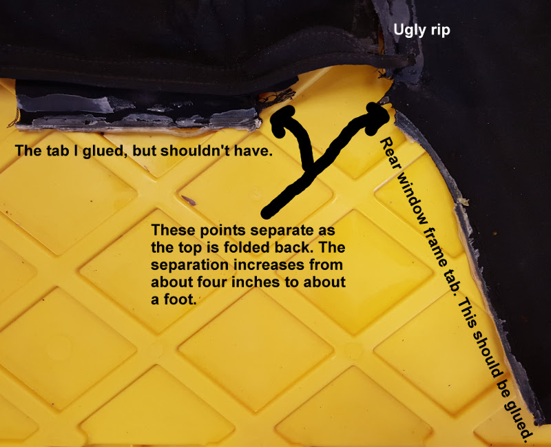
Here’s a video that shows the action of the frame — and why the top tore. Note the way that the top end of the rear-most window frame piece separates from the rear end of the piece over the window. There is a short piece that bridges these pieces of the frame around the window. Initially that short piece separates the parts I glued by about four inches, but when the frame is put down, those pieces set about a foot apart.
Here’s a picture of the fateful tab on the torn canvas top, labelled as “The tab I glued, but shouldn’t have.” I really don’t know why the manufacturer of the canvas top would have included a tab at that position, since it quite obviously fit the frame piece above the window, and it seemed designed to be attached. On the replacement (vinyl) top I got, the area above the window frame was reinforced with a vinyl piece about the size of the tab I had fatefully glued, so it could be that the manufacturer of the canvas top wanted the tab just tucked back as a floating protection for the top above the window.
In any case, there was no arguing with the physics of the thing. It tore. The video and the picture should tell the story.
While I was investigating the reason for the failure of the canvas top, I revisited “andyzaks” instructions that I found on E-type Lovers (http://www.xke-lovers.com/). These are good instructions, and I followed them through again — in dry run fashion — to see where I might have diverged and made my error. I came to the conclusion that I was misled by the “fateful tab” that apparently didn’t even appear on andyzaks’ top when he was putting his on. Key thing to note is that the tops on the Series 1 cars are fastened at the front, back, and at the rear of the window frame, where the chrome finisher sits.
I decided to do a video of the process, and it came out pretty well, though I realized after going through the whole exercise that doing a video is harder than writing up a blog post! If you listen closely you’ll probably hear Christmas music in the background at times. That’s a dead give-away for when this top was installed!
The car is going on the market in late January 2016, very likely. I have been planning for this, and I’m getting to a point where I think I have a realistic plan in mind. I do wonder about selling it when I take it on my little drives around Rougemont, but I think I want a new project to sink my teeth into.
Oh, I think I’ll do a few more videos as time goes on. Videos are an interesting medium, even though they are a little more tedious to put together.
This one is for Aaron, who is now off on his own in Mooresville. And this is the last web entry for the fifth year of restoration; the next entry will start the sixth year! Maybe the sixth year will be the year of driving the old beast.
If a picture is worth a thousand, words, I thought, why not try a video? Well, I’m sure it’d be worth another 10,000 words or so, but the camera we have is very, very old. Fifteen-second
videos is about all it can handle, and that doesn’t quite cut it. However, take three 15-second videos, and maybe you’ve got a shot at, say, the equivalent of 2,500 words. So that’s what we’ve tried here. A before the start video, a start video, and an (inadvertent) after-the-start “Woo-Hoo!” video. The actual start video, as you might note by the absence of ear protection, doesn’t quite fit the sequence. It’s actually the second start, not the first — a historic recreation, as it were.
But this was really, really fun! More fun than we’ve had with the car in ages and ages. More fun than … even spraying color (as we did almost exactly four years ago)!
There were some extraordinary requirements for this start. First, the starter button (charming thing), still won’t play well with the solenoid. I believe this is a matter that has more to do with the starter solenoid setup than the starter button. I checked out the button and all is well. The wiring diagram for the solenoid seems straight-forward enough, but I have to wonder about the “downstream” things like the coil and the mysterious distributor. It could be that the poor solenoid is expecting some downstream happenings that, well, just aren’t. The result of this confusion was that I couldn’t just press the starter button to have the engine come to life. I had to hotwire it. A simple matter of taking the starter wire and bridging the solenoid leads manually.
It works just great, and should be a lesson in how easy it is to steal a car like this. Thirty-seconds under the hood and you’re driving it.
There are also some very loose ends — quite literally — that have to do with the wiring. As the good XJ6 folks on Jag-Lovers told me, I needed to fit an amplifier to the distributor in order to get spark. I figured that it was best to make sure the system worked before making the necessary fittings for the amplifier, and so I have temporary wiring in place for the amplifier. On an XJ6 from the late 1970s and 1980s, the amplifier was grounded to the body, and I’ll need to make sure that the grounding is suitable for this piece. The wiring from the distributor to the amplifier is fairly short, probably about 10 to 15 centimeters, so the fitting needs to be in close proximity to the distributor. The leads that run to the coil are not that long either. I haven’t done it yet, but I am going to fashion a metal bracket that will hang on the left subframe forward, near the picture frame junction. The bracket will be partially obscured and hang on the engine side of the frame. It won’t be up to concourse standard, but the engine will work (and reliably, I hope).
The video of the actual start makes it appear that it was just a matter of doing the hotwiring, and after things were set that was the case. I was amazed at how quickly the old engine came to life. (The cylinder head redo probably had some influence on that, of course.) Getting to that point was a bit painstaking, since Aaron and I wired the distributor badly. We consulted the shop manual that showed the old 22D distributor in its illustration, and we took the illustration a bit too literally. We identified the wrong connection on the AB14 cap as belonging to cylinder number 6 — the frontmost one. The confusion had to do with the different orientation of the vacuum advance on the 22D and AB14 setups.
The result was that our wiring was off by one. And the result when I tried to fire thing up was a bit disconcerting. Instead of a popping, exploding coming-to-life, the engine became a several hundred pound flamethrower. Flames poured out of the exhaust manifolds, sometimes mustering a bit of an explosion. But, alas, no joy. I managed to singe the hair off my right arm in my starting attempts.
In order to set things to rights, I focused first on the carburetors, since the thing seemed to me to be set extraordinarily too rich. They seemed OK to me, though I know they’ll need tuning. Manipulation of the distributor timing just didn’t work. I then did things the right way, and turned the engine to 12° to 14° before Top Dead Center (TDC) markings on the crankshaft dampner. That orientation should point the distributor rotor toward the setting for cylinder six. And when I looked, the error was immediately apparent. We had the wires offset by one plug. Fixing that was as easy as moving wires over.
With the wires in the right place, the engine immediately came to life. Totally amazing. Wonderful to witness.
The thing is loud without an exhaust system coming off the manifolds. I can hardly wait to fit that, so the characteristic Sir William’s Six Symphony can ring around Rougemont. But the exhaust system will need to wait for a bit. I’d first like to set the things straight that are dangling on wires. There are also a couple of coolant leaks that need attention.
I wish that Aaron had been able to be on hand for the initial start, but he was able to hear the engine via a telephone connection. He’s moved to Mooresville (north of Charlotte) to attend the NASCAR Technical Institute. He said he could tune the carbs, and I believe he could, especially after he has that training behind him.
More on the ignition system
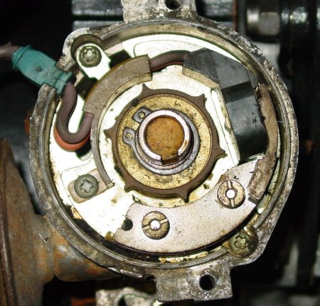
Peter Crespin mentioned on the Jag-Lovers XJ forum that he likes the AB14 distributor, and now that I’ve looked at it and read a little about the physics behind it, I think it makes sense, too. There really isn’t much to go bad — at least as far as moving parts are concerned. Aside from the parts that spin (and do so deep within the engine), nothing touches enough to do anything counting as friction. I’ve reused the picture from the previous web page to illustrate this. The star-shaped round thing spins, of course, but it doesn’t physically touch anything to its sides. The influence is little more than a purturbation of, well, mysterious tiny things or, as the physicists would have it (at some times and other times, not), waves. I don’t know, as I suppose it matters which way you’re looking at the thing … so Professor Heisenberg. The main thing is it causes spark. (If you’re interested, head to the prevous web page and click on the links associated with “reluctor” and “Hall effect.” Probably read the Hall effect article first, and don’t sweat the mathematics.)
Spark was a bit elusive, simply because I hadn’t a clue about what I was dealing with, except that the innards of this distributor didn’t look very familiar. I needed another part to complete the setup — an “amplifier” that sits between the distributor and the coil, with the two leads from the distributor heading into the amplifier and two wires out heading to the coil’s positive and negative posts. David Boger had the piece, and he shipped it to me pronto.
Sure enough, the system is the AB14. The Lucas label proclaimed it.
I hooked the amplifier up by just plugging it in, and I hoped for spark. But, nope, there was no joy, not even a little cold burst of electricity. A little study of the amplifier itself was instructive, though. The mounts on the back are quite purposeful; they’re little triangular outcroppings that convey solidity and contact. So I figured that the housing and the little triangular mounting parts were intended to serve as grounding points as well. A quick grounding wire attachment was all it took. I had ground and spark.
This was one time when I think reading the instructions would have been nice, but I got by with good counsel from the folks at the forum and a little critical thinking. I have gathered enough little bits of evidence to lead me to believe that the engine was a late 1979 year product, very likely an engine that would also have a home in a 1980 model year car. I recall that the donor car was a model 1979, but the build date might have been late. It might have sported some features that would be common in the following model year. Peter Crespin wondered out loud whether the setup I have was an early AB14, and I know when I got the replacement distributor cap, the NAPA fellow told me that it was “actually” a 1980 model cap. I suppose I could investigate with a little bit of work.
But, heritage questions of a replacement engine are much less important than the fact that the thing turns, works, and is loud without an exhaust system!
 I’ve reused the picture from the
 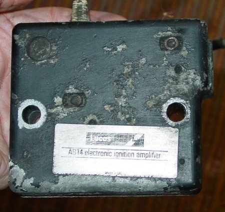 the donor car was a model 1979, but the build date might have been late. It might have sported some features that would be common in the following model year. Peter Crespin wondered out loud whether the setup I have was an early AB14, and I know when I got the replacement distributor cap, the NAPA fellow told me that it was “actually” a 1980 model cap. I suppose I could investigate with a little bit of work.