The heading says “front suspension,” but for all practical purposes it should read “torsion bars are the key — and the pain.” I have a vague suspicion that a great number of
 restorations go swimmingly until torsion bars need to be dealt with. At that point, the would-be restorer throws up his hands in defeat and carts the car to a professional, or the garage becomes as silent as a crypt.
Like it or not, torsion bars and the parts that meet them make up a lot of doing the front suspension. As I found out, if you don’t prepare these parts before you assemble, you end up breaking things down and rebuilding. The truly bad thing about the torsion bars is that you’ll have to mess with them quite late in the game — when you have everything together and need to adjust them.
The shop manual I use has useful exploded views of many of the assemblies on the Jag, but it struck me as odd that the exploded view of the front suspension was spotty about the location of nuts and washers. The ball pins, for example, seemed to float freely without a washer or a means of affixing them to the assembly. I was thankful for my scrupulous photography during the breakdown of the car. Since the suspension was literally doubled — left and right sides — I could usually find a shot that showed what I needed.
I was fortunate enough to lurk on Jag Lovers E-type forum (http://forums.jag-lovers.org/) to read through active discussions of front suspension issues, and especially torsion bar installation. That helped greatly, though I didn’t find an opportunity to pose any questions. They were, for all practical purposes, already addressed by the assembled wise guys. Or my questions resolved themselves with some careful looking.
Perhaps you won’t make the mistakes I did.
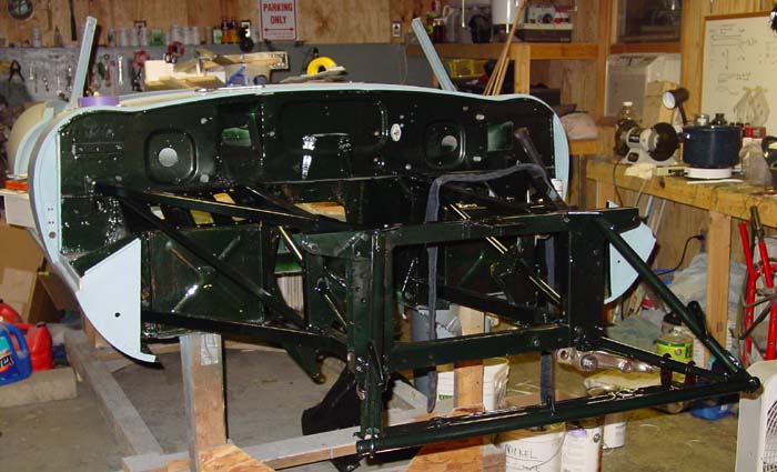
This more or less distills the process of how I installed the front suspension. I have illustrated the text in the sidebar. This process comes after installing the front suspension (or at least one side of it) not once but twice. I managed to make enough mistakes to warrant dismantling my work and starting over. Overall, the key is to make sure you understand the subtle differences between the parts on the lower wishbone assembly. (Yes, the forged front wishbone levers do fit only on one side in spite of their seeming identity.) And the other big point is preparing the splines on the torsion bars and their splined fittings. Remember, you will be revisiting the torsion bars later when it comes time to adjust them. Later, of course, means after you’ve already got most everything else installed — and therefore haven’t much room left to fuss over the bars.Actually, I dread the thought of adjusting torsion bars later on down the road.Oh, and in all of this please note that “your mileage may vary” — use this narrative and the pictures to guide and inform your better judgment.
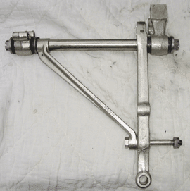
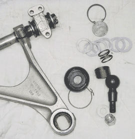
Assemble the upper and lower wishbone assemblies.
This means inserting the fulcrum shafts and loosely attaching the brackets with their bushings already inserted. For the upper assembly, you can loosely fit just the bush and bracket part of the front bracket. That bracket has two parts, one of which you attach to the picture frame separately. Both front and rear brackets need to be loosely fitted onto the lower wishbone. I had mistakenly assumed that I could attach the lower bracket on the picture frame (the largest of the front suspension brackets) and then slide the fulcrum shaft into place. I found out this is either impossible or, if not impossible, hard to do without chipping away at paint and otherwise furiously banging.
Lower wishbone assembly.
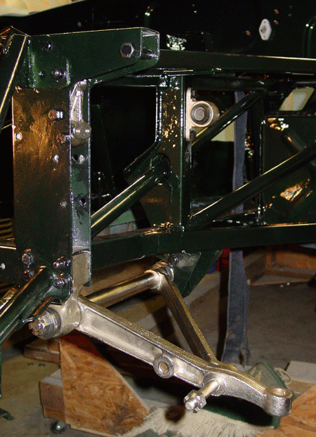
The lower wishbone goes together quite easily. Mind the washers, especially those that sit between the bush and the castellated nuts. These are very close to the size of the washers that fit the upper wishbone assembly. Closer inspection shows that the hole for the lower wishbone washers is slightly larger than the washers fitting the upper wishbone. I had to scare up one of the special washers from Stefan Roundy, who called them “distance washers.” I was missing one for the upper wishbone and another for the lower. These are quite thick and they sit on the side of the bush opposite the castellated nut. The lower wishbone, as far as I can tell, has only one of these washers, located at the rear end of the fulcrum shaft. The front lever of the assembly — the part to which the torsion bar attaches — apparently doesn’t have a washer between the bush and the cast wishbone part, which is quite wide and flat on the side facing the bush in any case.
The fulcrum shaft for the lower wishbone is not symmetrical. One end has a longer section for fitting the wishbone part and the bush than the other, by a few millimeters. The longer of the two ends goes to the rear.
Although the “rear wishbone lever” (the tapered bar extending from the rear of the fulcrum shaft to the front lever) is for all practical purposes identical on both sides of the car, the “front wishbone lever” is specific to a side of the car. The difference is at the end with the splined hole that receives the torsion bar splines. The front-facing side of the bar is machined to be slightly indented. If you put the lower wishbone lever on the wrong side of the car, the lever will bang against the subframe, and probably cause damage.
At this point you actually begin preparing for the torsion bar installation. Using a triangular file (get a new one so it’s sharp), clean out the splines on the lower wishbone levers, inside the fitting that goes on the rear end of the torsion bars, and on the front and back ends of the torsion bars. This is tedious but it made all the difference for me, and I believe it will pay off in future adjustments. I didn’t do the cleaning for the first installation of the front suspension, and I found that the torsion bar installation was simply too difficult. I could get them in place, but the thought of having to adjust them was a nightmare. I figured I’d break everything on the lower wishbones down and start over. (Jag Lover’s was helpful here, since discussion of torsion bar adjustment was active at the time.)
File the fittings and the bars until you can place the bars into the splined holes without having to use anything more violent than a rubber mallet. You do not want to do too much filing so that the bars fit sloppily. They should be snug, but adjustable.
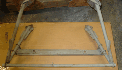
Upper wishbone assembly.
The front mounting bracket for the upper wishbone has two main parts, one that attaches by three bolts to the picture frame and the other that holds the bush. These two parts are attached by means of three 5/16 24 NF grade 8 bolts. Shims may or may not sit between these parts.
The rear mounting bracket fits directly to the side frame with two bolts and nuts. On the inside of the frame, where you attach the nuts, there is a stiffener sitting between the nuts and the frame. This bracket might also have shims. You can tell the difference between the stiffener and the shims by noting their shape. At least on my car, the stiffener had squared corners and was noticably thicker gauge than the shims. The shims had rounded corners, were thinner metal (26 gauge, perhaps), and one of the holes for the bolt was in fact more of a open-sided slot, making a “C” shape. The shims, of course, fit between the frame and the bracket.
It is easiest to attach the rear bracket and bush and the piece that fits to the picture frame separately, since these parts are situated such that you can slide the remaining wishbone assembly into place. (This unlike the lower wishbone which needs to be slipped into the subframes with brackets already attached to the wishbone assembly.)
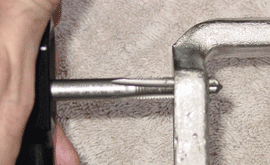
Insert the fulcrum shaft into the wishbone by slightly loosening the adjustable holes on the wishbone (one of the holes is threaded). Do this by inserting a screwdriver into the groove and spreading the groove slightly. Make sure that your screwdriver doesn’t extend into the hole itself, since that can either obstruct the fulcrum shaft or even damage it as you are inserting it. The fulcrum shaft goes into the threaded hole first with the threaded section of the shaft going in last, of course. I found that applying a bit of grease to the threads was useful, though I was also careful not to smear grease on the shaft. You do need to exert some pressure to screw the shaft through the threads, and there is a period when you don’t have access to the notches on the shaft. Those notches are for using a wrench to turn the shaft for adjustment.
I brought the threads through the hole and didn’t pay much attention to how far. Fine tuning the geometry of the front suspension comes later.
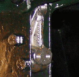
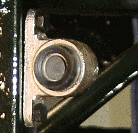
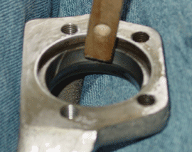
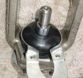
Upper wishbone ball joint/pin installation.
The ball joint/pin fits into the top of the upper wishbone, with the pin extending down through the oval-shaped hole below the chamber that holds the ball-shaped end. The ball pin is held in place by a concave fitting pressed on the top of the ball and held in place by a spring. The spring is pressed by a disk covering the top of the ball pin chamber in the wishbone. The disk is held in
place by a circlip or, also called an “internal retainer clip” or a “snap ring.” The pin part of the ball pin is threaded, and a rubber boot protects the pin and exposed sections of the ball recessed inside the wishbone. This boot is held in place with an external wire ring that wraps around the base of the rubber boot and presses it into a groove on the wishbone.
To begin, it’s best just to clean the ball pin chamber on the wishbone, especially the bore that will accept the circlip. This groove surrounding the upper part of the ball pin chamber has a tendency to get clogged with residues from plating, rust, and general grime. If you don’t get this clean before putting things together, it’s a little tougher to clean up without sliding everything apart.
Apply a small amount of grease either to the ball pin where the pin and the ball meet or to the inside portion of the oval hole at the base of the ball pin chamber in the wishbone itself. This should lubricate the lower section of the ball pin after it is placed into position. Then insert the ball pin into the chamber. The ball is pressed down by a short cylinder with one concave end. The concave space has a hole in the center of it. Grease the top of the ball pin or the inside of the concave surface, and place the concave surface into contact with the top of the ball pin. (My kit came with the concave fitting already coated with waxy grease, and I added some.)
Place the spring on top of the concave fitting. Now comes the hard part. You need to press the cap down and insert the circlip. I used two small “Visegrip” welding clamps to hold the cap in place. I think the ideal would be to use a wheel puller-type tool to press the center of the cap, but I don’t have one … yet. I found that a key here was to make sure that the garage door is closed. I ended up losing a circlip because it flew right out the door and the only other one I had also sproinged into oblivion. As a matter of fact I had to order not one set of circlips, but two. I mismeasured and ordered the first set too large. They are 1 3/8-inch. (If you need some 11/2-inch circlips, let me know. I’ve got 25 of them.)
You can put the cap on anytime after you’ve installed the upper ball pin and associated parts. I installed the caps after I had fit the “uprights” and the torsion bars (basically everything else was done but the caps). I did that so that I could bear down on the cap. I can see that installing the caps before mounting the upright onto the upper and lower ball pins would make that installation easier. Once installed, the cap keeps the ball pin from spinning too freely, so it’s easier to get the lock nut on the pin.
The rubber boot goes on easily. Slip it over the pin that is now extending from the wishbone, and slip the wire retaining ring over it into the groove on the boot. I used a piston ring expander to expand the ring, though the tool probably wasn’t necessary.
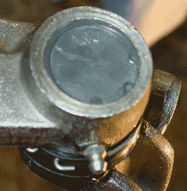
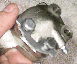
Lower ball pin installation on the “upright”
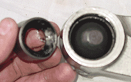
The lower ball pin fits into the bottom section of the so-called “upright” which is the part that connects upper and lower wishbones and accepts the stub axel and the brake caliper. It is slightly larger than the upper ball pin. The kit I used contained a steel alloy ring that fit into the large hole on the upright. It also contained a plastic retaining cup that really had no place to go in the assembly on my 1963 E-type. I assume it was used on other cars using the same type of ball pin setup. The installation process is similar to the installation of the upper ball pin, except it is perhaps a bit easier because the ball is held in place by a steel cap that is held in place by four bolts. You don’t need to fuss with a circlip.
I cleaned up the threads for the bolts using a 5/16 24 NF tap and wire brushed the hole where the steel alloy ring was to go. I let the steel ring sit submerged in engine oil for a while before inserting it from the bottom of the upright. Using a small piece of hardwood as a soft “punch,” I tapped the ring into place without any problem. The ring should fit firmly. The ring should extend about three millimeters or so on the top side of the hole. There is a small groove surrounding the ring where the rubber boot fits.
Insertion of the ball pin is quite similar to the process used for the upper wishbone installation: you apply a small amount of grease and insert the ball pin. Noteworthy in the design of the steel ring is a small groove that extends in a curve inside the ring, on the face where the ball and the ring meet. When I first saw the groove I thought that perhaps I had received a damaged ring, but it turned out that the other kit had an identical groove. I then realized that the groove was an intentional design to allow grease to move from the lower section of the ball joint assembly — really where the grease fitting is — to the upper area of the assembly that is covered by the rubber boot.
Tin shims fit between the body of the upright and the conical cap. My kit included four thin shims and one slightly thicker one. I installed the shims one at a time, tightening the four bolts each time, until the ball pin was movable. One thing that got in the way of the cap installation resulted from the clear coating I had applied to the nickel plated parts. I had to sand off the coating so that the shims and the cap would sit true.
When you have the correct number of shims in place, remove the bolts, place the bolt locking inserts, and reset the bolts. I didn’t bend the bolt locking inserts around the bolts (and won’t until everything is unambiguously correct). I put in a new grease fitting, too. It goes into the cap.
A small note: I was able to use the original BEES bolts on the cap, and only had to replace one of the bolts. I was particularly proud of my zinc plating job on those bolts. They really look quite good — too bad they’re placed where practically no one else in the world will be able to see them!
The last thing is the easiest. Slip the rubber boot over the pin that is extending from the upright now that it’s in place. Put the wire ring into the groove at the base of the boot. I used a piston ring expander to expand the wire, but this can probably be accomplished without a tool.
Joining the wishbones with the upright. This is, perhaps, the easiest of the tasks (and because of that, I’ve not illustrated this section with photographs). Basically the upright is attached by inserting the pins in the appropriate places. The upper pin in the wishbone goes into the hole at the top of the upright, and the lower wishbone has a hole into which the lower ball pin fits from below. The kits I used include new nuts with nylon “locks.” I found that the nuts went on nicely until the nylon hit the threads, and then the pins had a tendency to spin. Since the pins are (mostly) held in place by friction, I used my rubber mallet to tap the wishbones, thereby setting the pins more tightly into place. This firmed up the pins so that it was quite easy to tighten the bolts. By the way, there are washers for every bolt on these pins. My lower ball pin kits didn’t include new ones (the originals are quite thick); the upper ball pin kits included new washers.
A note on greasing the ball pins. I chose not to shoot grease into the upper and lower ball pins until after I had completely finished the assemblies. I did this because I wanted to be able to remove the upper and lower ball pins more easily if I needed to, and greasing them might have made removal more difficult because of spinning. I didn’t need to remove these again, but I think holding off on the grease is prudent. You just need to remember to grease before you do any sort of serious movement of the suspension.
Torsion bars. I have to admit, torsion bars are not my favorite things in the world.
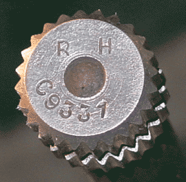
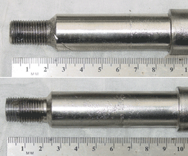
The torsion bars are labelled for right and left. You’ll see “R H” and “L H” on the front end of the torsion bar (the end with the groove crossing the middle of the splines). Although the right and left bars will indeed fit on either side, switching them may invite failure of the bars, so put the “R H” on the right and “L H” on the left. I believe this has something to do with the way that steel adapts to tension — as long as it is consistent, the steel holds, but wrenching the torque the opposite way (as when you put the right on the left, and vice versa) weakens the steel.
The key is to make sure that the splines on both ends are clean and rust free. They should slip into their receivers on the wishbone and on the rear bracket without too much whacking. As a matter of fact, being able to slip the torsion bar splines into these parts without a rubber mallet is desirable. But you do not want to make the match “sloppy.” I learned in getting my torsion bars ready that if you drop a bar on a cement floor, you can expect the splines to have been altered slightly enough to make refitting into a wishbone or bracket more difficult (though not impossible, thank goodness). The moral: If you drop it, check it. Also, any amount of whacking with a steel hammer is likely to change things, so use a rubber mallet whenever possible. If you must use steel to hammer, find the indentation on the end of the bar, insert a punch into it, and then “drift” the torsion bar back and forth into place.
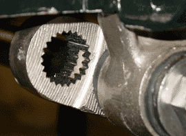
Use a triangular file to clean up the splines on the bar and in the receivers on the wishbone part and the rear bracket. Insert the torsion bar frequently to test the fit, and be sure to rotate the bar in the parts, since you’ll be adjusting the tension of the bar by rotating the bar. It needs to fit any number of positions, not just one. A note on adjustment: the torsion bars can be adjusted very finely, it turns out, since both the rear and front splines can be set. There are 25 rear splines and 24 in front, making the adjustment possible to a tiny degree. Besides, you can’t accidentally insert the rear splines into the wishbone receiver — unless, of course, you really mess up the splines.
When you’re ready to put the torsion bars into place, fit the rear fittings onto the bars, so that they swing loosely around the bar in front of the rear splines. Then insert the rear splines into the large hole on the frame where the torsion bar fitting rests and move the front part of the torsion bar into place in the splined hole on the lower wishbone lever. I found that I could gently rest the bars in place without completely inserting them before putting some grease on the splines and the holes.
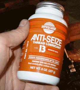
The Jag Lovers E-type forum mentioned the use of “anti-seize” grease for the torsion bars, and I decided this was the way to go. I have used a regular old lithium grease, but I believe I’m going to move toward a “multi-purpose” grease in the future. The anti-seize formulas include metals, and the one I got was based on copper, which I gather is common among anti-seize products. My guess is that one brand is as good as another. I applied the anti-seize grease to both the torsion bar ends and the fittings they were to go into. It’s quite messy stuff — as thick as glue or river-bottom mud. The bottle I got had a brush in the cap for applying the stuff.
The torsion bars fit nicely, without too much work. I used a rubber mallet to tap them into place from the rear, and then after the front fitting was secure, I moved the rear fittings into place. I have put a couple of bolts into the rear fittings just to hold them in place. The set up by no means is able to hold much weight, but that’s not a concern right now. I plan on finding my torsion bar reaction plate and putting it in place. I haven’t seen that part since I installed the new floors some time ago. I want to make sure that the reaction plate is in good shape with the new torsion bar set up. After that is checked out, I can remove the reaction plate for more permanent installation after the engine is in place.
I remember that getting the reaction plate out was an ordeal. I hope putting it in isn’t — though I have a feeling it will be a job that is joyful only after it’s complete.
I’ll return to the front suspension later, when I’ll take on fitting the stub axels, brake calipers, steering couplings, and all the rest. I figure this will take a while.
 I thought about calling this section “Sproing!” because of the trouble I have had with the upper wishbone “circlips” (also known as “snap fasteners” or “internal retainers”). I got new upper and lower ball joints/ball pins for the wishbones, and the upper kits were supposed to have included internal retainers. And one kit did, but the other replaced the internal retainer with an external retainer, which of course wouldn’t work at all. I fetched the old part that I removed that had the internal retainer and I figured I was set.
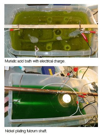 to a plater in Fayetteville, North Carolina — all sixty-some pounds of them. I was hoping that I’d be able to get an estimate and shake hands on the deal when I was there. I wasn’t in any particular rush, especially since I has seen on the web that this particular plater “took his sweet time.”
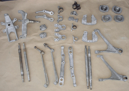
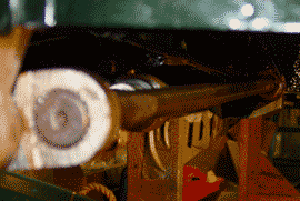
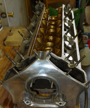 When my dad was here, we inspected the tappets that accept pressure from the cams. One of these
  appears to have been damaged either by dirt or by corrosion. The surface of the plate where the cam touches has been pitted. This will probably have to be replaced, since a roughened surface like that will certainly wear the cam and also be significantly weakened itself. The other tappets show almost no wear at all. My dad says that the cams bear the most pressure of any parts in an engine. They look to me to be models of precision and efficiency.
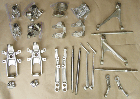
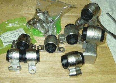 Caswell Plating and do the front suspension mounting brackets. The brackets fit into the subframe and really need to be installed at the time when the subframe is fitted. The pieces have surface area below the 16-square-inch per ampere of current that nickel requires. I was able to cobble together DC power sources to make about an amp, so 16-18 square inches was about the limit. Plating nickel is indeed easier than plating zinc. The electrical charge doesn’t have to be quite as precise, I think, for nickel. And, perhaps, experience counts a bit in plating. I was very pleased with the results.
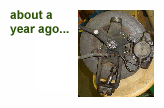
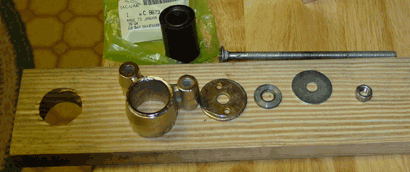
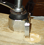 to the frame with three bolts that go into a fitting attached to the frame, sometimes slightly spaced with shims. These three-bolt brackets won’t lie flat on the surface of the wood, so I made a slight indent with the drill bit so that the piece would lie flush to the wood at the point where the bush was inserted.
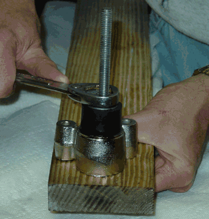
 through Florida to see relatives and participate in a travel exchange with people in Sarasota. I was a little worried about suggesting that we take on a project with the old car, since I didn’t want to impose my restoration work on an unwilling participant, but it actually turned out that Dad wanted to do exactly that.
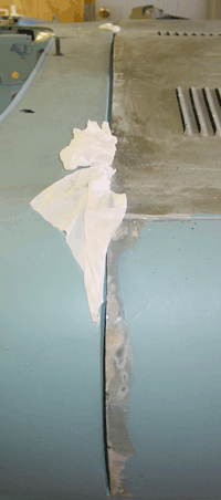 bonnet fit against the lower sections of the bulkhead and the upper sections. Things were slightly wider at the upper part than at the lower, meaning that we could raise the bonnet to even things out.
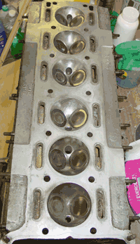
 roots. The initial spray appears later in this page.
 out that 77RW was Opalescent Dark Green, too. I mentioned that I didn’t like the color of a Opalescent Dark Green car I’d seen on the Classic Jaguar website, but I noticed as well that photography of the color varied enormously. You can’t get a picture of what the color “really” is, since that is part of the charm of an opalescent/metallic paint. The dark green seems to play with light especially well, and it appears nearly black in some light and glimmeringly dark green in other light.
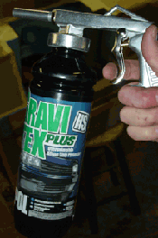 in abundance this winter, you just want to hunker down and get through it. So I occupied my restoration time with things that were easy to do in short and less cold moments. Little things over a long period do add up. This is a two-part addition to the restoration journal. Welcome to part one….
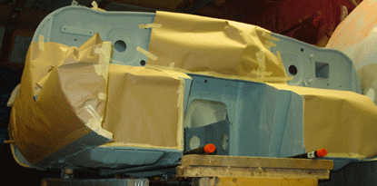
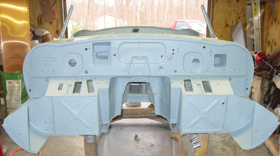
 I left the undercoating for a week or so before spraying a thin coat of primer over the surface. This may have been unnecessary, but auto paint folks suggested it for good sealing and for a uniform color beneath the paint.
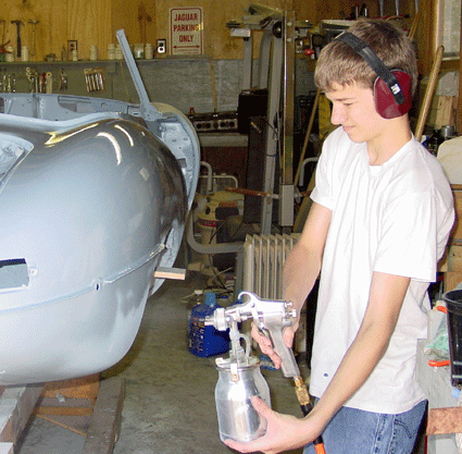 warm temperatures to open up the garage and spray the body shell with primer. The temperatures reached the mid-70s (Fahrenheit, 20+ Celsius), and so short sleeves did it, as you can see from the picture of Aaron spraying the right rear quarter panel. As everything was open and the fan was blowing, we didn’t use face masks, which probably weren’t necessary in this case. But we did wear ear protection because the compressor is so loud. In retrospect, I believe we should have worn our respirators, too.
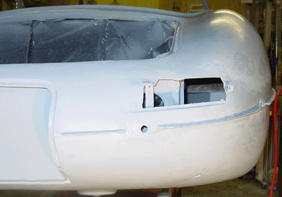
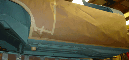
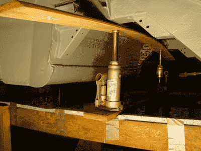 garage has been nice and warm, and I have been able to do some more priming in shirt sleeves. As a result, the entire exterior and the body shell underside is primed. (Actually, there are small portions of the underside that need some primer — the front portion of the footwells that sit on the crude frame I made to hold the body.)
 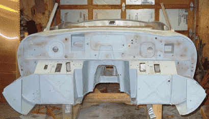 Anyway, the jacking opened up most of the space along the beams and all of the trunk floor for priming. As I mentioned, only the front footwells still need priming. So, after I’m done with the trunk floor, I’ll get those primed. I figure that I’ll get the “Rock Schutz” rocker guard on the edge of the trunk before I lower it, though.
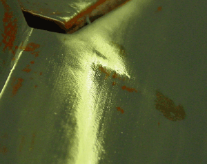 Detecting the dent — Why light is your friend
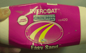 The filler I’ve used for this final work is “Easy Sand” by Evercoat. Bill McKenna mentions it on his ’63 E-type FHC restoration website, and I found it at the local auto parts and body shop supply. The chain automotive stores, around here at least, don’t have it in stock. It is very good stuff. The filler comes in a tube-like bottle (see the picture), so dispensing it is easy and creates no mess at all. Like other fillers, Easy Sand is a two-part product, so it should be durable. The filler itself is very fine and goes on very smoothly — it’s more a cream than a putty. The manufacturers say it bonds well to metal, plastic, and primers.
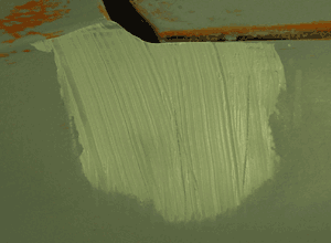 I’ve always doubted whether the stuff would stick to primer, so I’ve ended up sanding right to the metal again. Also other fillers often sand badly when they are adjacent to buildable primer. The stuff usually is slightly harder than the primer, and so you have to be careful about outlining your filled area with a low spot in the primer. (Good blocking usually makes this less likely, though.) The Easy Sand product blocks very nicely.
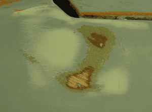 Block the area after the filler has cured. The area should be noticably better, though it might have a few imperfections. I noticed on this repair that I missed a small tap dent that I created while tapping down one of the high spots. It was not a particularly big dent, so I figured that the buildable primer would take care of it You can see the effect of the 60-grit sandpaper on the area. The two original high spots have merged to become one elongated spot, now flat from sanding. Flanking low spots have been filled with the filler. There isn’t very much filler left in the area, which is as it should be.
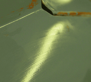 After the filler is blocked, it’s time to reprime the area. I use a paint brush to apply the primer, and that works quite well in small areas like this. After the primer is dry, block it again. This should bring the area to where you need it to be. I did this small repair after the second primer coat was blocked, and the problem was apparent. (This door has been a real job, and this little fix was nothing compared to the rest of the smoothing that was required. The big work was the result of many minor ripples all over the mid section of the door. That work was tedious mainly because getting the lines straight was complicated by the large surface area.) Any imperfections in the primed surface of the repair will get a at least one more going over before the surface is ready for color. I check the light line of the repaired area to see where it needs more attention. As you can see in the bottom picture, it’s in pretty decent shape, though it has some slight indentation yet. This will be taken care of in the next round of primer coat and blocking.
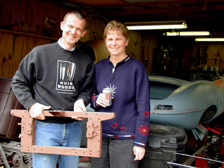 much new to report, though I will post some photographs after the Christmas Holiday week. I’m taking most of the week off, and perhaps warmer temperatures will be a nice Christmas gift to us this year. One thing that is needing some handling is a high spot on the right door. I’ll document the handling of that little detail, since there is a little difference in body correction at this stage in the game, that is, during the final points of priming and preparation for “spraying color.”