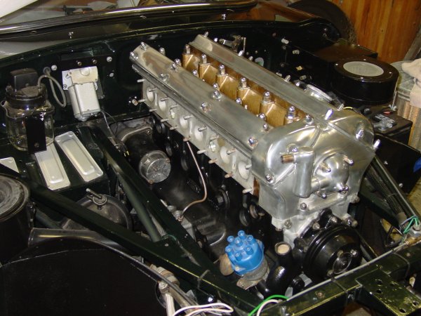
I wanted the engine to go in this fall, and it did! Aaron and I fiddled with the fit of the torsion bar reaction plate — the bane of the removal of the engine renewed in reverse! — and the next day slipped the engine into place. Here’s how it looked just after it was put into place.
The actual installation was on my birthday, so it was a very good day. As a matter of fact, I think it was my best birthday in years.
Aaron and I dropped the engine in from the top. Bill McKenna opted for the bottom, and there is some feeling that the bottom-up method is easier than dropping the whole hulk from the top. When we took out the engine the first week we had the car (over five years ago!), we lowered it and lifted the subframes to allow us to pull the engine and transmission forward. I recalled fighting with the motor mount brackets to get them to clear on the way down, so this time we put the engine in from the top. My father had warned about chipping the paint on the subframes, and so we put a couple of layers of masking tape on the frames. The tape did provide protection from the inevitable bumps.
It is a fairly tight fit from the top, and you do have the raise the engine high enough that it feels a little scary. The touchiest part is tipping the tranmission end down, though the hoist we have includes a nifty worm-geared adjustment that makes pitching the engine angle a matter of turning a crank. The process of setting the engine into place really amounted to easing it into place by gradual leveling of the engine and lowering it in steps. We did have some extra — perhaps even necessary? — wiggle room because we did not have the crankshaft pulley attached to the crankshaft dampner. (I actually haven’t bought it yet.) This meant we had a couple centimeters to play with when the oil pan was just below the top of the picture frame.
Not only has the engine changed…
It’s fair to say that the engine would still be sitting on the floor in front of the car were it not for Aaron, who worked to resolve some of the fitment issues that I had wrung my hands about over the past several weeks. Literally, I had fretted about things so much that I had avoided doing much to resolve the issues.
Well, I had actually fretted not so much about things in plural as a specific thing: that terror-inducing construct having to do with the torsion bars. As I’ve said before, I hate torsion bars. And our experience five years ago with the torsion bar reaction plate still is amazingly fresh in my mind. The thing was a beast to get off, especially since we were cramped under the car and hadn’t really too deep an understanding of the dynamics of the front suspension. The role of the reaction plate in the front still seems a little mysterious to me, since it has been claimed that the reaction plate actually imparts something between the two torsion bars, allowing them to communicate in some advanced engineering sort of way. Perhaps. All I know is that the plate goes in after the engine is in place, and the plate either fits or it doesn’t, since the fittings just won’t give.
To make sure that the reaction plate was going to fit, I actually used it to set the location of the two halves of the replacement floor (right and left), but that was before the POR-15, undercoating, primer, and paint. The coatings made enough of a difference that additional futzing was required. Believe me, it takes very little to make the reaction plate tighter than works well. Bill McKenna had to do the same, he reported, though he used a grinder to take off the excess powder coat and such. Aaron and I didn’t resort to that, but we did whack and bump a fair amount. I suspect that professionals might actually take better account of the coatings when they use the reaction plate to fit new floors. I didn’t think of that when we were installing the new floor panels.
It’s important to get all of the bolts fitted without having to contend with the engine and transmission, so if you’re doing a restoration like mine, fit the reaction plate before dropping the engine in. That little extra time will take hours off the work.
We took the tension off the torsion bars, of course. It actually isn’t that bad a job to do, but it is a hassle — seems too much a sideline in relation to the real show of the engine going in. And, of course, there’s no graceful way to get at the bolts for the torsion bars and the reaction plate once the engine is occupying all that space.
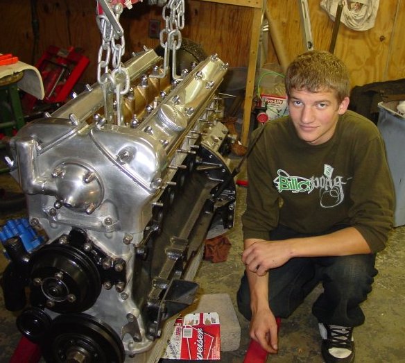
I was struck at how much Aaron has changed from the time when we first took the engine out (and he had managed to mangle a bronze bolt or two) and the time when we put the new engine in. Pictures say it all. He’s grown up to be a handsome man.
I’m now beginning to collect the parts I need to do all of the cooling and fuel and ignition work. Cooling hoses are the first thing on the list. I’ve found that bringing the old hoses into the parts shop works just fine. Gates replacement hoses are available, and Mike Frank has published a list of them. I’ll add to the options with another list in the near future. Several of the old hoses are either Jaguar replacements or (heaven forbid!) the originals. They’re in pretty tough shape.
I actually have the engine pretty much complete. The value covers are still off (more on that sometime later) and I need to get a crankshaft pulley (really, a matter of ordering it, but more on that below). I figured that I had some catching up to do, and the compression ratio tests seem a good place to start.
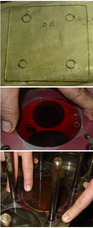
Figuring out the compression ratio. Top picture is the tool. The four large holes are for the studs, and the two small ones are for pouring in the liquid. The middle picture is the head measurement being taken. The red over aluminum is multipurpose grease I used to seal the plastic to the head. And the bottom picture is the measurement of the volume of the top one inch of the bore. For the head measurement, I used colored water; for the bore measurement I used motor oil.
Ray Livingston has developed an easy way to find out the actual compression ratio on XK engines. There are a few measurements that are required, and a little fabrication is necessary. That fabrication consists of making a plexiglas cover for the bore and hemispherical head space. I made mine with scrap plexiglas that we had laying around.
With a nice request, Ray will supply the spreadsheet that required to interpret the results of the measurements, and the very good instructions he sends with the spreadsheet include how to take the measurements with the head in place or not. So, it’s entirely possible to chase down the pinging problem of your XK-engined Jaguar with the head in place and Ray’s instructions in hand.
The plexiglass tool serves one purpose: it levels out and holds liquids that are poured into the bore and the hemispherical chamber in the head. You need to drill holes to allow the head studs to go through (if you haven’t taken them out), and you need two holes to manage the liquid you use to measure capacities. One of these is for liquid to go in, and the other is for air to come out. I made the piece by just cutting a square of roughly the right size and then laying it on the inverted cylinder head to locate the stud holes and the two liquid-related holes. The two small liquid-related holes should be at the edge of the bore or chamber. You can use the stud holes to affix the plexiglas when you’re doing the filling with liquid, but I found that a firm press with my fingers was just easier to manage — I figured I’d spend more time making the part than really was necessary.
The principle is to measure the unknown volumes by filling them with a liquid. Obviously, the volume of the cylinder head’s combustion chamber can be altered with machining. You shave your cylinder head to truth, and the effect is that the combustion chamber shrinks ever so little. You do the same to your block, and the bores get just a little smaller in volume.
The process for me was very simple, since I had the head off. Ray provides instructions for measuring with the head on, but pay close attention to his warnings and directions.
With the head off, you need the plexiglass tool, some grease (for sealing liquids in and the plexiglass tool on the surface of the head or block), a dial indicator to measure the space at the top of the bore at Top Dead Center and to set the piston at exactly (Ray’s emphasis) one inch from the deck of the block, a “telescoping gauge” to measure the width of the bore, a vernier caliper, and an accurate measure for the liquid. Ray suggests something called a “burette” with about a 100 ml capacity, but I didn’t have anything so fancy. Instead, I got a 100 ml graduated cylinder from my friend Laszlo, and that worked just fine, though I had to pour the liquid rather steadily. If I were doing this test frequently, I’d probably find a burette. Ray suggests using mineral spirits, too.
I started with the head, and I used colored water as the liquid. (I figured colored water would be easier to see.) I put some grease around the chamber and around the valves. A spark plug was installed, too. Once I pressed on the plexiglass tool, the grease acted as a glue almost. Lateral motion of the plexiglass was possible, but lifting it off the face of the head required some effort. As the chamber filled with water, I was careful to press the plexiglass tool down against the face of the head, so there wouldn’t be (that much) extra liquid to fill any space made by the float of the tool over the grease.
Measuring the bore is a little more complicated, since you need to measure the distance from the deck of the block to the top of the flat part of the piston at Top Dead Center. A dial indicator and a mount is needed. Then you bring the piston down one inch, wipe some grease to seal the piston and bore, and do the liquid trick. For the bore measurement, I used motor oil. That was a little challenging, since it is viscous and your measurement can be confounded by the fact that oil sticks to the side of the graduated cylinder. Also, the surface tension properties make it a little tougher to read the level of the oil. You have to take the bore width measurement, too.
At any rate, I ended up taking measurements at least twice, and in the case of the head, probably four or five times before I was satisfied. To get a result all you do it plug the numbers into Ray’s nifty spreadsheet and choose a head gasket thickness. I’m using the “Payen” composite gasket (0.035″ thick), and I came up with a compression of 8.31:1. Remember, I have the 8:1 pistons in this engine.
The amusement of buying used parts
The XJ6 has different pulley styles from what I originally had. (Pages on differences of the 1963 3.8 liter engine and the 1979 XJ6 4.2 liter engine are available for the cylinder head and block.) My 1963 E-type had “double groove” pulleys, and the crankshaft pulley was entirely different, both in bolt holes and in fit. The crankshaft vibration dampners are different from E-type to XJ6. So, I was off in search of a new crankshaft pulley. People the the Jag Lovers forum suggested Classic Jaguar as a source for new, and indeed that was the case. But I wanted to check out used part sources. I have exchanged emails with “Marius” at Marguar Jag parts (an Ebay vendor), and he’s been responsive though hasn’t had the parts I’ve needed. Since he didn’t have the correct pulley, he suggested I contact Geoffrey Reis at Jag Connection. That ended up generating an amusing email exchange that I publish here in entirety.
From: geoffrey@jagconnection.com
Subject: RE: 4.2 crank pulley, E-Type, "double grooved"
Date: July 17, 2007 10:24:26 PM EDT
To: Mark R DeLong
Mark. If a phony reproduction pulley is selling for (and worth?) $95, why would the real thing, which is unreproduceable accurately, be worth less than that? It makes no sense, and actually shows me that I've underpriced my pulley. So, if you want it, take it now. The price goes up to $130 on Friday. Thank you, Geoffrey
-----Original Message-----
> From: Mark R DeLong
> Sent: Tuesday, July 17, 2007 8:28 PM
> To: Geoffrey
> Subject: Re: 4.2 crank pulley, E-Type, "double grooved"
>
> Thanks for the reply, Geoffrey. I found a new aluminum pulley from Classic
> Jaguar (http://www.classicjaguar.com/per9.jpg) for $95 plus shipping. I'd
> be willing to pay you $70 plus ground UPS. Let me know if that's OK, and I
> can Paypal or whatever.
>
> m
>
>> On Jul 17, 2007, at 1:00 PM, Geoffrey wrote:
>>
>> Hello Mark,
>> Yes, we have a pulley with two grooves. $100 plus shipping would do
>> it. Call if you'd like; tonight is best. Thank you, Geoffrey Reis at
>> Jag Connection.
>>
>> -----Original Message-----
>>> From: Mark R DeLong
>>> Sent: Saturday, July 14, 2007 9:04 PM
>>> To: geoffrey@jagconnection.com
>>> Subject: 4.2 crank pulley, E-Type, "double grooved"
>>>
>>> Marius from Marguar Jags said you might have some parts, he didn't
>>> have what I needed and forwarded me to you. Do you have a crankshaft
>>> pulley that fits the 4.2 dampner and has a double groove? I have an
>>> XJ6 (1979) pulley, but it's not the double grooved variety. I need it
>>> for an E-type.
>>>
>>> Thanks.
>>>
>>> m
Well, Geoffrey didn’t get my business, but I do believe others can find a pulley from him for $130. Two weeks from now, it very likely will cost more, so it would be good to hurry. Me? I’ll be happy to get a pulley from Classic Jaguar, an item which is hardly phony and a good replacement for something that is, after all, accurately reproducable.
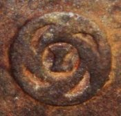
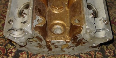
You know you’re not in 1963 anymore when you see that drain swirl logo of British Leyland in relief on the block. It’s enough to make you think twice about your angle grinder and whether you’re enough of an artist to rub off the metal smudge. Of course, in October 1978, when this new engine of mine was cast, British Leyland — or “BL” — was the colossus astride nearly all of British automobile manufacture. At that time, Jaguar has been in the BL fold for a decade, and the conglomerate included nearly all of Britain’s formerly independent marques: Jaguar, Daimler, Lanchester, Mini, Riley, MG, Morris, Wolseley, Austin, Vanden Plas, Rover, Land Rover, Alvis, Standard, and Triumph. In the early 1980s, BL’s long-troubled history led to its unravelling. Jaguar was spun off and became independent with a stock offering in 1984. The remnants of British Leyland changed its name in 1986 to “Rover Group,” which of course has had its own history of disintegration. (At least it now is much more international, I guess, since BMW bought Rover and perhaps thought better of it. MG Rover is now Chinese rather than British.)
It hardly needs mentioning that Ford took up Jaguar eventually, spent a lot of money, and now appears to be setting the company up for the vacuum cleaners of private-equity investors.
At any rate, the logo of liquid(ity) going down the drain is on the right side of this engine block. However, the familiar “JAGUAR 4.2 LITRE” marks sit more centrally and more prominently smack in the middle on that side. That label is where it should be and where its like had been all along.
The left side has as its distinguishing characteristic the oil dipstick fitting. That feature is so undistinguished that I haven’t spent the time worrying whether it is the same as the 3.8, though I believe it will be prudent to use the XJ6 dipstick at first, just to make sure that the oil levels are correctly measured.
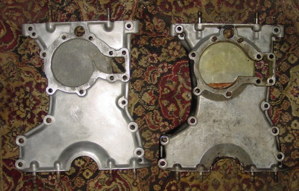
Differences of timing covers and water pump impellers
I was told that the timing cover was a drop in, but I was actually hoping that the water pump was instead. There are differences, beginning in 1969, of the capacity of the pump’s innards and the size of the water pump impeller. Also, the semicircular cutout for the crankshaft end was a bit wider — oddly, I thought. We actually checked the crank for signs of wear and checked for free play. But the more glaring difference was the water pump void.
Timing chain covers, E-type and XJ6. The E-type is on the left, and the XJ6 is on the right. Although the two covers are hole-identical and have identical studs, the main differences are in the water pump area. The XK water pumps after mid 1969 had larger impellers and were “deeper.” I used the original cover, since I wanted to use the old pump and its belting system. One change that we noticed, and that is still a bit mysterious to me was the machining around the frontmost edge of the crankshaft semicircle on the XJ6 cover. It was flared on each side. I believe this was be design and not from wear, though I don’t know exactly what might have been the purpose. A different seal?
Now that the 1963 version of the timing chain cover and water pump are fitted, I do have to admit that the newer design looks better engineered, with probably higher water throughput. I chose the original because I feared that the forward extension of the XJ6 water pump was too much. The later water pump is bigger overall, and the belting for the XJ6 is more complicated, but there isn’t all that much space between the front of the engine and the back of the “picture frame.”
Differences of oil pan and sump plumbing
The XJ6 oil pan is significantly different from the E-type’s. It has a blubous protrusion that extends off-center toward the right. The oil intake from the sump comes up near the rear on the XJ6, while on the E-type, the sump intake is centrally located. I wanted to keep the XJ6 sump, actually, but I was concerned about clearance in the subframes. I asked a couple of people about the fit, and Dick Maury let me know about the fit problem of oil pan and the sump intake, and he let me know of some of the adjustments that come with the changes on the oil filter mount. He has been around the block (and through some slalom courses) with his Jaguar cars, including a modified 1971 E-type.
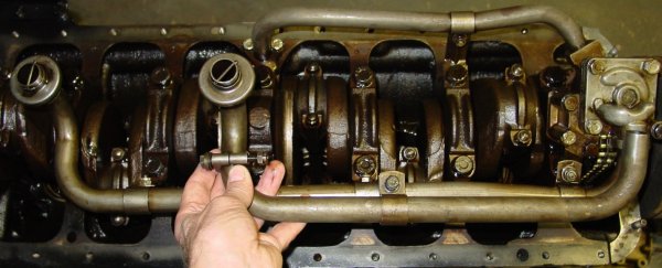
Oil pickup pipes, XJ6 and E-type. I’m holding the pickup pipe from the 3.8 liter E-type above the setup on the 1979 XJ6 4.2 liter. You can see how much farther back the XJ6 pickup pipe goes. The E-type oil pickup is centrally located. There is a small bracket just above my thumb on the E-type pipe. I removed that before installing it.
The E-type sump intake pipe is quite a bit shorter than the one on the 1979 XJ6, which pulls oil from the large deep collector at the rear of the oil pan. But interchange is easy, since there is only one pipe to worry about, and it’s the same diameter for the E-type and the XJ6. The oil pump on the 4.2 liter engine is said to be better — larger capacity or better efficiency, I believe — but that makes no difference as far as pipe sizes. Bill McKenna’s very correct restoration of his 1963 E-type coupe included a 4.2 liter oil pump — one of the very few deviations from the 3.8 liter setup he did. Bill commented in his report that he had to make some changes to the “oil pickup pipe,” though I didn’t have to make any changes.
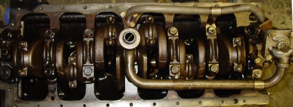
The E-type oil sump pipe in place. The pipe was a good snug fit, and I used the brackets from the original XJ6 pipe to fasten it. I don’t know what changes Bill McKenna had to do to get his 4.2 liter oil pump installed, but I didn’t run into anything peculiar.
It’s literally a five-minute job to replace the long pipe for the shorter E-type pipe. The original 3.8 liter oil pan is a drop-in fit on the 4.2 liter block and will fit in the car with the original oil pan, though it might not with the XJ6 pan. (An aside: I probably would have stayed with the XJ6 pan if I could, because it seemed to me to have larger capacity and the oil uptake looks to me to be a bit better thought through. It is, of course, a quite noticable deviation from the 3.8 liter oil pan design.)
Oil filter mount differences
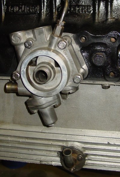
1979 XJ6 4.2 liter oil filter mount. There are several changes from the 1963 3.8 liter engine that appear in the oil filter mount. The cam oil feed comes off the top of the mount, rather than from its own hole in the block, as is the case on the old 3.8 liter block. The pipe for the oil pan connection comes off the rear part of the mount on the XJ6 instead of at the bottom. That change means some fettling, of course, and that’s not in this photograph. And, of course, the mount is designed for modern spin-on oil filters, thank goodness. To the right of the mount you can see the holes for the XJ6 motor mounts.
The oil filters change much for the better between 1963 and 1979. The old felt filter replacements gave way to nice and easy spin-on filters. The oil filter mount on the 1979 engine is ready to accept a regular modern filter.
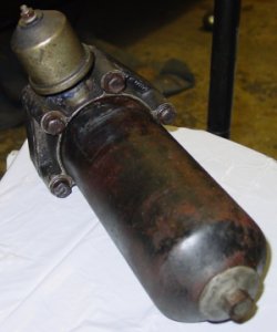
The old felt-insert oil filter. This huge thing is the oil filter setup for the old 3.8 liter E-type engine. There are spin-on adapters available from several vendors, but the 1979 XJ6 engine has the spin-on filter setup already in place. See the oil pressure sensor on top of the filter mount.
And beyond the simple change to spin-on filter mounting bracket come, of course, the complications. On the 3.8 liter engine, the hose to the oil pan comes right off the bottom of the oil filter bracket, and so the hose run on the old engine is straightforward — though (as many have noted) it’s complicated by different outer dimension pipes fitting to each hose end. On the 1979 XJ6, the rubber hose is only an inch or two, connecting to a pipe running to the bulge in the pan that caused me the worry about fit into the subframes, since it extends fairly far to the right. On the XJ6, this pipe heads to the rear, and so the fitting on the oil filter bracket heads toward the rear. The upshot is that the run from the bracket to the oil pan pipe mount is a little contorted when you use the E-type oil pan and the XJ6 oil filter mount. Surely it’s not a straight shot. Dick Maury told me that he used an XJ6 engine in his race car, and he took advantage of the hose changes to fit an oil cooler. It’s a tempting thought, but I don’t think I want to add a complication at this point.
On the old oil filter mount setup, the oil pressure sensor comes off the top, and on the XJ6 the sensor is on a separate aluminum block mounted to the rear of the oil filter mounting bracket.
The XJ6 oil filter mount has the connection for the cam oil feeds as well. It is on top of the mount. Dick said that it is possible to add the connection in the regular E-type location (on the lower rear left side of the block) by drilling and tapping a hole, but this XJ6 setup suited me just fine. The XJ6 block casting, by the way, is flat where the cam oil feed oil would go, so this would be a small alteration for a machine shop to accomplish.
The 4.2 liter block has some mounting differences, though the block itself was designed as a replacement option for earlier XK engines, too. So there is (mostly) backward compatibility for earlier setups, sometimes slightly ingenious ones.
Motor and other mounts
Just forward from the oil filter mount there is a significant change from the old E-type setup. The motor mounts on the XJ6 are set farther back — more or less centrally on thge block. But, this is no big deal, because the tapped holes for the old E-type motor mounts were retained on the XJ6 and used for other purposes like the power steering pump and air conditioning compressor (I believe).
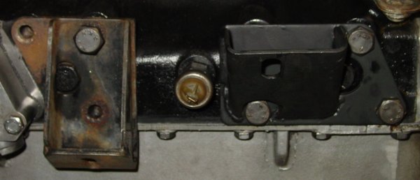
XJ6 and E-type motor mounts. Just forward of the oil filter mount is where the XJ6 motor mounts go, while the E-type mounts are set right at the front of the block. The picture shows both mounting brackets in place, with the loosely fit, rusty one being the XJ6 version.
It’s really just a matter of putting the E-type motor mounts in their correct place. — A straight and simple bolt-in job. (I’ve never Ebayed a thing in my life, but I might give it a whirl with these excess XJ6 parts I’ve got.)
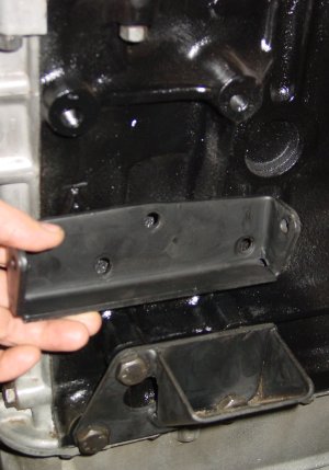
Old generator mount bracket won’t work. That’s my hand holding the old generator mounting bracket in the approximate place it would go. The 4.2 liter block doesn’t include the holes for the old generator bracket, so you have no choice but to upgrade to the alternator. I suppose it would be possible to create a bracket that would do the trick, but the question is why? The place for the alternator bracket is apparent — just above the bracket are two tapped holes.
However, when you jump from the old 3.8 to the newer 4.2 liter, you pretty much have to say goodbye to your generator, not that you probably wouldn’t mind that in any case. The generator bracket holes are completely missing on the 4.2 liter block. On the 3.8 liter block, these holes are placed just above the motor mount holes. On the 4.2 liter engine, the alternator mounting bracket fits much higher on the block. (See photograph on the left for what the 4.2 liter block holes look like.)
I’ve learned from a few telephone calls and emails that the 4.2 liter E-type alternator mounting bracket is pretty rare, unless you’re willing to use a bracket for cars with air conditioning. There are two part numbers for the bracket, C25158 for the Series I and C30615 for the Series II (both for non-air-conditioned cars). I called one fellow who deals with Jaguar salvaged parts, and he told me that he didn’t have any but that the brackets are available from the Usual Suspects. Then he then laughed and said, “But I bet you were trying to avoid having to use junk.”
Oh, well. I guess I might have to use junk — pricey junk at that. Or, I’ll get the part and make a non-junky replacement myself and Ebay the replacement with the excess XJ6 parts. It really depends on whether the new part I need turns out to be of lower quality than I want, I guess. The issue of part quality has been coming up quite frequently on restoration forums, and not just the forums devoted to the Jaguar marque.
The alternator upgrade (or at least “changeover”) has been well documented. It involves changing the ground from positive to negative. You don’t have to stick with a Lucas alternator, which is a blessing, I think. AC Delco alternators have been used (and it seems to me that Classic Jaguar has offered an upgrade kit using an AC Delco unit). Ray Livingston has described a way of using a Hitachi pickup truck alternator for an upgrade of the 3.8 liter setup. This requires a special bracket available from XKs Unlimited (part number 08-0399 in their 2005 catalogue, p. 316). But the same processes would work for installing a Hitachi on a 4.2 liter engine, using a standard alternator bracket. Ray’s documentation is available from XKE-Lovers (PDF).
Speaking of mounts, I got my parts from Terry’s Jaguar Parts, and I got new motor mounts, a bushing for the upper engine mount, radiator mount bushes, and a new fuel sump gasket from Motorcars, Ltd. The engine of course, is practically ready to have the transmission mounted, so this restoration journal entry is still behind the curve, so to speak. I’ll trade timeliness for some thoroughness. And there are some issues still to be dealt with — adaptations for the old (nicer) value covers, the crankshaft pulley, and of course, the alternator. So, there are still things to square up before this one runs.
As a side note before launching into depictions of the 3.8 and 4.2 heads, I discovered in my reading that Jaguar wasn’t the first to have bored out the 3.8 (or, maybe, the 3.4) liter engines to 4.2 liter displacement. It was reported that race teams had done so well before Jaguar decided to bore the XK to the max. If that was the case, I think Jaguar’s design for the 4.2 paid more attention to cooling than a race team could have. The major differences between the 3.8 and 4.2 liter versions of the XK seem to me to concern cooling.
Essentially, the cylinder heads are the same with the expected differences from the placement of the bores for the 3.8 and the 4.2 liter displacement. It’s quite apparent that the XK block couldn’t have gone any bigger than 4.2 liter, by the way. The bores are tight. The cylinder heads differ in the way that they handle cooling, though.
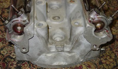
On the intake side, the XJ6’s 4.2 includes additional holes for coolant to be passed to the manifold. These holes may well be in the 3.8 head, too, though they seem to have served as a way of clearing the casting before they were plugged.
The only physical alterations to the 1979 XJ6 cylinder head were plugging these coolant holes with Dorman plugs (number 555-020) and removing an emissions control device (see below). Otherwise the head looks to me to be quite close to the earliest 4.2 and 3.8 liter versions perhaps except for some coolant holes at the rear and a somewhat stouter casting in the front timing chain area. Of course the machining was also slightly different for the hemispherical chambers for the differently sized engines, but the external intake side was similarly machined to accept the intake manifolds, one piece for the XJ6 and three-piece for my SU setup.
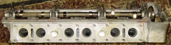
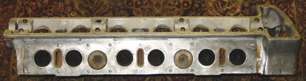
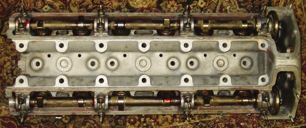
Here, as below, the top picture shows the 1979 XJ6 head, and the bottom shows the 1963 3.8 E-type head.
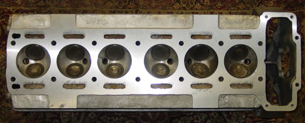
XJ6 4.2 liter head, intake side. The two round coolant holes were already plugged with Dorman 555-020 inserts before I took this picture. With the exception of those open holes, the XJ6 head is machined the same as the 1963 3.8 liter head.E-type 3.8 liter head, intake side. The holes that were later used for coolant were plugged with threaded inserts in the 1963 3.8 liter head for the E-type. Other Jaguar models using the 3.8 liter head may have used the holes for coolant, but I haven’t looked into that.
The top of the 1979 head sports six holes on the plane where the spark plug holes are located. They sit on the left side of that surface and are positioned between the holes for the left-side head bolts. These holes are for an emissions control device, lines for which attached to a manifold and had an attached heat-deflecting barrier. I’ve been told that this emissions device is commonly removed on XJ6s of the time and the holes plugged. Actually, when we removed the lines and the fittings from the head, they were hopelessly plugged with grime so I doubt they served any purpose. The holes led into the exhaust side of the head. They might simply have been intended as a means of speeding warm-up.
The three plugs on the XJ6 head were unbranded Dorman-like inserts. The 1963 3.8 head used bolts to do the plugging. I believe these holes were for clearing the cast. The 1963 head gives the impression that the bolts do some reinforcement work, and even if they did not, the process of threading the holes for these inserts (and, for that matter, for the holes on the intake side) must have taken some time and care. Certainly that required more work than inserting plugs into the XJ6 head.
XJ6 4.2 liter head, top view. No paint on this one, and as a matter of fact very little worry about appearances. Grinder marks were plainly visible. Note the plugs in the three cast clearing (probably) holes and the emissions control device holes offset from the spark plug holes. Otherwise, from the top the 4.2 head looks just like the 3.8 liter E-type head.E-type 3.8 liter head, top view. The gold paint is a bit taken off from the head cleaning, but the polished aluminum and the paint dress up this head. Instead of pressed in plugs, threaded bolts fit into the three holes along the head. Otherwise, there’s not much besides the emissions device holes on the 4.2 liter head to distinguish this one.
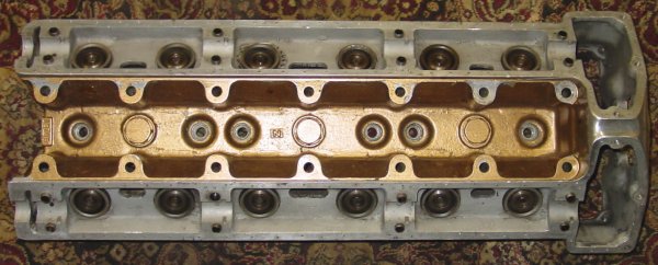
Bottom’s up, the head is nice and true, just back from the machine shop. At the rear end of the head, there is a major difference from the 3.8 head. The 4.2 liter head has two coolant holes that appear in an extension of the cast, at least when it’s compared with the 3.8 liter head. The 3.8 liter head more or less has a flat rear wall, while the 4.2 liter head flares out as it meets the block. Of course, the bore locations vary between the 3.8 and 4.2 engines. The XJ6 head has twelve additional coolant holes that are inset more to the midline of the head, fore and aft. These small holes roughly meet the block where a machined cut sits between the bores. Coolant going through those cuts certainly was effective and the cuts themselves probably allowed for expansion in the metal between the bores. (I’ll probably take some pictures to illustrate this difference when I muster up the strength to move the 3.8 block around a bit.)
The 4.2 liter head also cut pairs of coolant slots in the outermost positions adjacent to the bores. I’m not exactly sure what the purpose of that was unless to strengthen the face a bit. The 3.8 liter head has large single slots in the same position. The 4.2 liter head looks a bit beefier. Walls are thicker in the front, and the hole sizes are smaller, yet there seems to be more coolant flow possible, and more directed flow at that. I’ve not weighed either head, but I’d bet the 4.2 would be noticably heftier.
XJ6 4.2 liter head, bottom view. The bottom is the most different from the 3.8 liter head, in that the coolant holes are more numerous both in real numbers of vents and by the addition of the two new vents at the rear and ten holes near the bores. It seems obvious that the engineers paid a fair amount of attention to cooling the 4.2 liter engine. In comparison to the 3.8 liter head, the aluminum casting is a little stouter, as the walls at the front timing chain cover show.E-type 3.8 liter head, bottom view. In comparison to its larger brother, the 3.8 liter head seems simple in design. Where the 4.2 liter head split long slots into two, the 3.8 let the casting have long coolant slots adjacent the bores. The small, near-bore coolant holes on the 4.2 are absent here. The casting is a little thinner on the front, and on the back wall of the timing chain cover, a small “V” is grooved in front of number six cylinder.
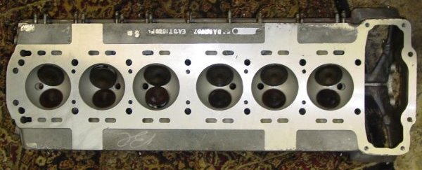
XJ6 4.2 liter head, rear view. Note the bulge and the extra aluminum in the casting at the very end. This bulge is where the additional two coolant holes fit. The rear end of the cam areas are a little different.
The extra metal on the rear end of the 4.2 liter head is easiest to see with the two heads side-by-side. This extra bulge is practically unnoticeable from the top, since it only flares out from the back face of the head about an inch from the base of the head. I don’t know exactly where the coolant goes within the head itself, especially since the internals of the castings are both quite airy — filled with voids at least. The two extra coolant holes that the extra metal allows must have served the coolant needs of the head itself, however. The holes are actually quite well removed from the cylinders in the block, and I have assumed that the flow from these extra holes would have be down from the head, probably originating from areas nearer the cams than the valves.
You can see one challenge in the new head — it doesn’t have holes for the bolts attaching the tach generator or serving to block off the end of the cam area. On the XJ6, the lower semicircular void was fit with a rubber plug, and the value covers lacked any semicircular cutout. If I refit the tach generator, it would probably be merely ornament in any case, since the cam end won’t drive the generator, I believe. I might drill and tap the holes, though. I don’t know if I want to put up with a make-do plug.
E-type 3.8 liter head, rear view. No extra metal here. The head ends straight off the back. Note the threaded holes to fit the tachometer generator (right side) and the hole cover (left side). The area around the cams are more subtly cast than in the 4.2 liter head.
I have an intake head gasket from the 3.8 — it looks to me pretty much the original, since it’s as thin as could be. And I have a new head gasket for the 4.2. I have yet to compare them, except in the most cursory fashion. The new gasket is considerably thicker, with metal rings fitting the holes for the bores. I thought about asking Ray Livingston for his special spreadsheet to determine actual displacement, but I wonder if it would apply on this engine. This one has 8:1 pistons, I’m almost relieved to say. Even with some shave off the head, the compression shouldn’t exceed 9:1, and least by much, and I’ll be running premium gas anyway.
Aaron got the upper end and bottom end gasket sets for me, and when I can retrieve a few tools from neighbors, I’ll be setting things back to rights. Terry’s Jaguar Parts is sending the last bits (as far as I know) and a cam setting tool. So, we’ll soon be good to go.
I’m hoping that the next entry will do the same job on the block and its accessories. I have learned that some 3.8 E-type elements will need to be refitted on the engine, and the oil filter fitting that I was happy to see on the new engine might actually prove to be a bit of a challenge.
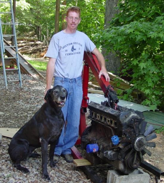
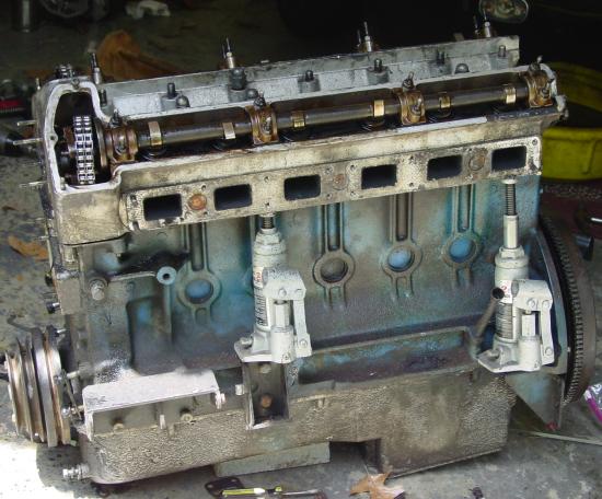
Very exciting! I picked up an engine to resolve the issues of the thrust washers and crankshaft. This one is a 4.2 liter XK from a 1979 model year XJ6. I used the free advertisement section of Jag Lovers to track it down. David Boger lives a little over two hours down interstate 85 from me, and so it was an easy pickup after we made the deal.
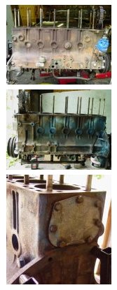
The engine is basically the same as the one that came out of my car, except that it was fuel injected (I didn’t need that) and a 4.2 liter. The water pump and belting is a little different, and (as the picture shows) the XJ6 has a fan attached via the water pump. It also has an electronic ignition, which I will keep. The block itself is configured a bit differently for the XJ6, since it uses the E-type engine mount points for the power steering pump (and something else on the other side). The XJ6 engine mounts are set a little further back. The nice thing is that you can still use the E-type mounts in their appropriate places — just remove te brackets for the other stuff and stick in the engine mount brackets. The cylinder head has a couple of extra holes for coolant, and some subtle changes that are less of a bother, probably. (See below for information about the head.) David provided the XJ6 exhaust manifolds that I’m going to try to use. The originals I have are fine, but I like the XJ manifolds, and I’d like to keep the heat shield in place, since damage to the bonnet paint over the manifolds has been reported.
David has about a dozen XJ6’s in his collection of parts cars, ranging from series one through three. He has a series one that looks like a good candidate for restoration — a right-hand drive model with some interesting details. It was damaged a little on an outer sill, but that was a pretty easy repair, I thought. He’s working on another XJ that’s perched on the ramp that you can barely see in the background of the picture. Instead of an XJ6, this one is an XJ12, with a front end full of metal. I don’t know what his ultimate plans are for the car, but it’s a good project. I think it would take me a long time to take on a V-12, though it would be fulfilling to complete … until you have to pay for the fuel, of course.
I walked his grounds, visited his horses, met his wife and 22-month old daughter. I determined he was a good man to buy an engine from. I certainly know where I’ll be able to find E-Type parts that might be interchangeable with the XJ series. And, seeing those old XJs made me wonder if I should try my hand at one of those eventually. I have an XJ8 (I think they call it an X308 model, or the like) now, and it’s a wonderful car. The earlier version XJ6 series has the same glove-like, natural quality. The interiors of David’s cars, though most of them were worn out, still had that Jaguar feel. In my opinion, the XJ6, series one through three, were nice cars, but the following boxy ugly version of the late 80s seems to have lost its way. Jaguar found the path again with the XJ model that currently is offered, I think.
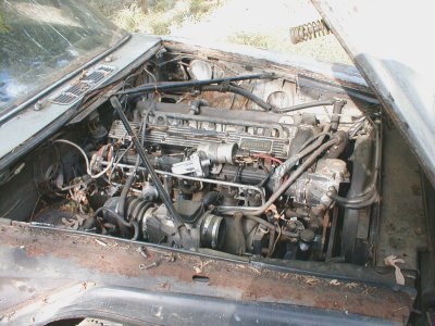
He walked me to pay homage to the donor car, which sat at the end of a row, sans rear suspension, front end akimbo, left front panel gone, lights poked out — all probably mounted on other rides somewhere.
David is a square dealer, and he offered me the history he had of the engine and its donor car, telling me what did and did not work. He lives near Rockwell, North Carolina, which is not too far from Charlotte. He’s probably most available by email: david@everydayxj.com. I’m adding him to my list of suppliers, since there do seem to be useful overlaps of parts between the E-type and the good old XJs. [Added 20 January 2008: David has a website now: http://everydayxj.com.]
It’s been striking to see how much the early E-type engines were ornamented. The engine block from the XJ6, cast and fitted during the dread British Leyland years, was crudely sprayed a faded blue. The cylinder head on our old cars were painted gold and the area covering the timing chains was smoothed and polished, or at least brushed. The XJ6 head was barely extracted from the sand after it was cast and then quickly gone over with a grinder to remove casting seeps. and seams. No cosmetics in the late 70s, I’m afraid.
The “bottle jack” method of cylinder head removal
In short, the cylinder head was a bugger to get off. The head bolts had corroded, except for the pairs on each end. I guess this is quite common. I first thought that the head gasket was giving us the trouble, but quick taps of the bolts (with head nuts fittted, of course) quickly told us which ones were locked tight. They were the ones that didn’t budge or rattle in the least. Aaron squirted bolt loosener (PB “Blaster”), and that seemed to help a bit, and we made tiny headway to free the corroded bolts.
But a quick search on Jag Lovers brought up references to a “bottle jack” method that appeared to be quite effective. I have to admit that I was a little baffled, but at least I had a couple of hydraulic jacks. They have done various and good service on everything from cars to ninety-year-old floor spans. Why not on a cylinder head, too? When I was sitting at the computer, I had no idea where the things would go, but with jacks in hand and kneeling next to the engine, it was apparent.
The underside of the head juts some way out from the top of the block, and the block itself has a shelf-like flare near the bottom. The jack sits between these points. The picture tells the story, at least in part.
I think that if you have four hydraulic “bottle jacks,” you’d have the best luck. I had two, and Aaron and I were constantly shifting them to push the head off more-or-less straight. I was worried that with too much uneven pressure the head could be damaged or the bolts even more fixed in place. If you had six jacks, you’d probably be able to take off a stubborn head with very little trouble. I would do one thing differently, I think. I would probably situate a stout angle iron under the head before applying pressure. That would spread out the pressure and eliminate any marks from the top of the jack. However, you would have to make sure that the pressure from the jacks would be going slightly inward. Otherwise the angle iron could pop out — perhaps dangerously, given the pressure that can be exerted.
I had intended on detailing the differences between the 1963 and 1979 cylinder heads in this entry, but I think I’ll delay that a bit, since we hurried the head to the machinists. When it comes back all fit and shiny, it’ll be a better example to look at in any case. I hope that the next entries might help some other restorer do a similar transplant.
I’ve been picking away at the engine. The cylinder head has gotten a clean bill-of-health after inspection, pressure testing, and a shave. The SU carburetors are cleaned up, though not quite ready since replacement parts are needed. Bores are all measured, and they have little wear from the last rebuild, when .030-upsized pistons were installed. I have debated whether I should just go ahead and have new sleeves fitted and go back to the nominal bore of 3.4252″. Since the current bores are still in good shape, I think I’ll wait to do the more thorough rebuild. I’ll fit new rings on the old pistons.
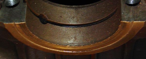
But there are still issues that trouble this engine work. Back when Aaron and I took the engine apart, we discovered the thrust washers unseated, with one of them sloshing around the oil pan. Their absence took its toll on the crankshaft and a part of the engine block. Pictures below tell the story. The crankshaft might be repairable, assuming that a good submerged weld could build up the face where the thrust washer fits. A ring-like ridge stands up about 0.045″ from the face where the thrust washer fits. I believe that entire depression would need building up. The ridge itself bit into the engine block in the absence of the thrust washer, and the are where the crankshaft met the block has been beveled slightly. That area would also need squaring up.
Obviously, the question in my mind now is whether the crankshaft is salvagable — or, for that matter, the block.
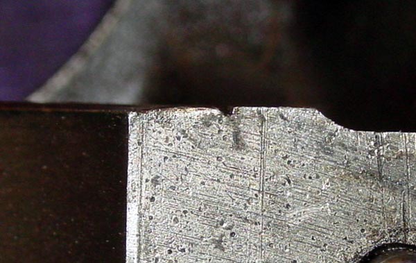
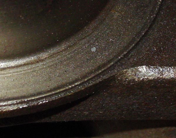
Face on block. It’s a little oily and dusty but at least not rusty. The side of the bearing seat shows a semicircular groove cut into the metal. This groove is about at the outer edge of where the thrust washer fits. You can see that the impact of the crankshaft created a ridge of crushed metal on the face that accepts the crankshaft bearing.Bevel on block. At the center of the picture it is apparent that the friction from the crank absent a thrust washer has ground the face into a slight bevel. This should be square, especially since the area serves to hold the thrust washer. This damage might not be that recent, actually, since it might be the reason why the thrust washer fell out. A relatively recent rebuild might have fit a new thrust washer in the damage section without repairing the damaged faces. The thrust washer we took out were beaten up by being loose, but they did not look particularly worn. The groove is easily seen, of course.The thrust washer face on the crankshaft. The ring-shaped rise is apparent in the photograph. The difference between the top of the ridge and the bottom of the depression is abut 0.045″. I actually think that the rise is about the correct height on the thrust washer face, though I can’t be sure. It’s still a mystery to me how the thrust washers are kept in position, unless they are capped in some fashion when the crankshaft is secured.
It’s about time to put the electrical decisions onto paper in a more presentable form. More methodical men than I would have rendered schematics first, traced everything to glassines in layers, and then passed the signed drawings to the next person for enactment … and, of course, improvization. The web pages that follow might even become my car’s electrical schematic. There’s always discussion about Joseph Lucas’s electrical setup for British cars, and I have dug up a quote that may or may not be accurately ascribed to Lucas. “Gentlemen do not drive after dark,” he is supposed to have said. If so, he can hardly have really been the Prince of Darkness, since he would never have been out in darkness, being a gentleman. And yet, I recall a warm night in or near the “scenic Flint Hills” of Kansas when the Lucas electrics in my MG failed and lights became weaker and weaker. I was just lucky enough to pull into an oasis on I-35 to let my battery recharge a while. That MG ate alternators.
I was too young to have been a gentleman, but I learned something about Lucas electrics.
When we removed the harnesses from the Jaguar, they all came out intact. The forward harnesses inside the bonnet and forward of the front bulkhead/firewall has been altered in part to resolve what must have been some starter alterations and to “improve” cooling. Otherwise, the wires were unmolested by owners or repairmen. Time had taken its toll on the cloth looming and cotton and plastic coatings had suffered from some exposure.
I’ve wanted to bring the car back to near what it was in 1963, except for a change of exterior color. But in part because of my old experience with Lucas electrics, I was willing to depart from the original electrical system — especially where the changes would be obscured from sight. I’ve not made all of the electrical decisions even yet, at least in the final connections. I have followed a few principles in this redesign:
Add fused circuits
Use relays to separate high and low loads
Minimize length of wire runs, if possible
Minimize use of connectors
Localize connectors to blocks
Upgrade wire gauge to runs with higher load
Use LEDS where it makes sense
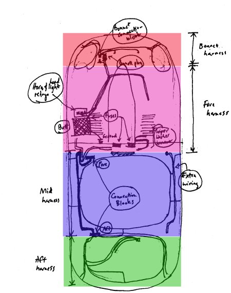
At this point, I have a total of 14 fused circuits, twelve of them emanating from the position where the fuse blocks are supposed to be, behind the center dash panel. The other two are for headlights and horns and are situated near the battery and next to the place where the relays for the horns and the headlight beams are located. These relays sit behind the left front wheel splash guard, directly in front of the battery tray. Those two inline fuses couldn’t be placed elsewhere without lengthening the wire runs from the relays forward. I figured it was worth the inconvenience of having the fuses in unusual places to fuse the headlights and horns separately and shorten the wire runs.
I’ve not mapped the locations of the original “bullet” connectors and connection blocks, but I know that in dismantling the harnesses the connections seemed to be everywhere. The wisdom of electrical troubleshooting on the E-Type seems to amount to checking connections and cleaning connectors. Connectors do deteriorate. I wanted to make sure that I could make as few of them as possible from terminus to terminus. I also wanted to concentrate the connections into specific locations.
The architecture of the car and its harnesses determined where the connection blocks should sit, and in fact a couple of them are originally in place. The “bonnet plug” and the internal connection block inside the bonnet are already in place. In essense, the bonnet plug connects one harness to another in a central location. That was the principle that I used in locating connection blocks. I installed two connection blocks — one underneath the left dash panel, near where the flasher is located. This connection block serves to connect the “fore harness” to the “mid harness” (see the illustration), though it also is often connected through the switches and such on the dash panels. The second connection block is inside the trunk and connects the mid harness to the aft harness. I departed from the locatiion of the mid harness by running it entirely along the car’s left side. Because there might be a need at some time to run wires aft through the passenger compartment, I added four wires along the right side. These terminate inside the trunk area and forward of the glove box. If I’m overcome by wanting to add an electrical whatever to someplace after, I figured I’d have a place to grab power or signal.
I’ve used spade-type connectors quite frequently, though bullet connectors still are to be found, usually to make the final connections to, say, a taillight or fan motor. And the complicated wiper motor connector block with its conflagration of bullet connectors is still there (though as yet, I’ve not connected them all up).
Purists might object to the departures. As much as I respect the gentleman, I’m not intending to make the car a monument to Mr. Lucas. I’m hoping that my little changes might keep the lights brighter.
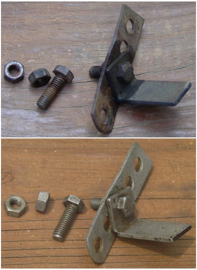
I read an article in Auto Restorer that claimed that molasses was a cheap but slow rust remover. I decided to give it a go, since I’ll have some rust to remove soon, and I do have some miscellaneous items that could bear a bit of a spruce-up and even some replating.
The test piece was a bit of metal that attached the exhaust resonators to the bracket. It was mostly a makeshift piece, but I did want to retrieve a GKN bolt from the assembly. The rest was just plain rusted and not destined for much other than the waste bin.
The article said that any molasses would do, but that the kitchen variety is a bit expensive. The virtues of this method is the lack of expense and the fact that you use materials that are not hazardous. If I go into this in a bigger way with other parts, I’ll probably use livestock feed grade molasses. I checked with our feed supplier (Wallace at Triangle Farm and Home down the road), but he doesn’t stock molasses, he said. I expect that the bigger farm supply north of us in Roxboro would have it. The recipe is simple. Dilute with between four-to-ten parts water for every part of molasses.
I used the Brer Rabbit brand we had on hand in the fridge, and diluted it to maybe about 6:1 water to molasses. I used dishsoap and water to remove what little oil and grease might have been on the parts (the top photograph was taken after the cleanup), and then I threw the parts into the molasses-water mix. That was on 25 June. I checked the parts midway through the week, and the rust had just begun to give way. I used a scrubbie pad to brush off the loose rust and popped the pieces back into the mixture. I did notice that the mixture had a foamy head, and I thought that perhaps the brew was beginning to ferment. It didn’t smell yeasty, though. Whenever I ran out to the garage, I gave the container a shake. By the weekend, the froth had faded, and it consisted of lines of tiny bubbles aligned, I assumed, above the parts. I suspect that whatever chemical reaction was taking place on the parts gave off a slight amount of gas.
On Saturday, 1 July, I used a wire brush on the parts, and it was clear that the molasses had done a job on the rust. Most of surface of the parts were rust free, and when I rinsed them and dried them, flash rust appeared alomst immediately. I left them in the mix until Monday, for a total of eight days of steeping.
The rust was almost entirely gone. I retrieved the GKN bolt with ease and put it aside.
I’ll be doing rust removal on the exhaust manifolds prior to getting them coated with whatever I finally decide, and I’ll use the molasses treatment. I went ahead and threw some rusty parts into the mix immediately after retrieving the test pieces. This process seems much safer for the environment (it’s said you can dispose of exhausted molasses mix on the yard!), and it is far less aggressive than other methods. The molasses mix should work for a while, but I don’t have enough experience with it to see whether the mixture just ages or whether the molasses mix simply gives out after treating a certain amount of rust.
Since rust removal is a constant concern of car restorers, I thought I’d pass this information on, devoid as it is of Jaguar E-Type specifics.
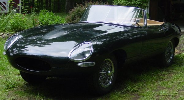
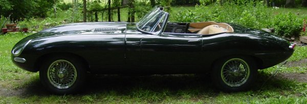
At last the car is on four wheels after almost four years of being suspended on a makeshift rack or jacks — or (in part at least) being encased in Ziplock baggies. Derek and I pushed it out of the outbuilding and into the little grassy area where a rose garden once bloomed, back when the car first arrived. The Opalescent Dark Green photographed well in these shots, but I had to contend with brightness. As a result the fire in the color seems to lack a bit.
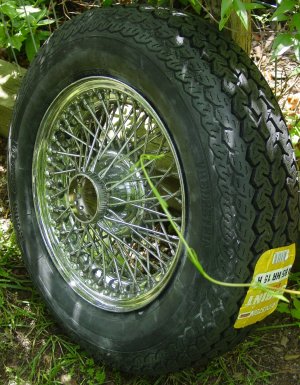
This side is the nice one, at least for the wheels. The wheels that came with the car were for a later model, and so I had to get the “curly hub” version. I went back and forth with buying completely new wheels, but I already had bought two used wheels and decided to try cleaning them up. They cleaned up nicely, and the few replacement spokes I installed got rid of a couple of spoke voids and a couple of rough looking ones. I was able to salvage a handful of the long spokes from a later model (not the “curly hub”) wheel. The shorter, so-called “bent” spokes were available from XKs. I decided to spend the new wheel moneysomewhere else — I’m sure to have plenty of places to drop the cash.
I went with Vredestein 185/15 tires, and I am very pleased with them — at least for their look and feel. I can hardly wait to discover how they drive. They came with pretty good reviews from other owners. I like the fact that they are pretty close to the right measurements in comparison to the original Dunlops. I now know more about tire “aspect ratio” than I thought I’d every learn. These tires sit “higher” off the rim than more modern tires, with a sidewall “aspect ratio” of between 75-80, I believe. Aaron did the wheel balancing at the Northern High School automotive shop.
At any rate the tires are handsome in blackwall.
The other side of the car has the rusty wheels that came with the car. I will probably salvage the best of these oldies to clean up, sandblast, and paint for the spare. But for the other side of the car, I’m going to watch for a couple of replacements that need cleaning.
The car is noticeably higher in the front, of course, because there’s no engine under the bonnet. But it is much easier to do the color sanding and polishing of the bonnet, now that the car is lower. When it was on the jacks, the bonnet’s performance bulge was quite a reach. The bonnet really needs color sanding, too. It seems that large flat areas of the car demand a great deal of attention because every little hint of orange peel pops out to the eye.
Why this is only “mostly” a rolling chassis
When I put on the rear wheels I made an important, though annoying, discovery. The real wheel hubs are on the wrong sides! The knock-off hubs just wouldn’t go on the sides that they were labelled for. When I put them on the side opposite, they screwed on nicely. I thought a few choice words, and I peered up into the IRS to see how difficult a job it will be to make a switch of the hubs. It shouldn’t be too much of a problem, and I should be able to do the job in situ. But instead of having a “rolling chassis” with a good portion of the interior installed, I’m stuck with having a “rolling chassis, mostly.”
Of course, you can’t just leave the hubs on the wrong sides, either. If you do, the rotation of the rear wheels would loosen the hubs, and you could find yourself in the weird circumstance of watching a wheel glide past you while you’re under way. (At least until your rear corner dips and you lose control of the car.) I now know yet another reason why splined hubs are a bit of a pain, in spite of the coolness factor they lend to the car.
Winter has been mild in North Carolina, though cold enough in the deep winter months to keep me out of the garage. March usually is the transition month — a month of teasing warmth and, when cold, a month of yearning for spring. This March has been warm. So warm, in fact, that this weekend I opened the front door of the garage to let air and sun in. This is what the car looked like on 11 March, just before the left door handle was put into place.
Please excuse the mess. Winter blows leaves through the cracks beneath a side door, but the rest of the disarray is my fault. I am always amazed to see pictures of other fellows’ neat and tidy workspaces. I’ve never been that organized, and I have kids who use the garage and the tools as well.
This entry might be a little too detailed for most folks, but I found that I spent an inordinate amount of time just figuring out how the door lock/latch mechanism works. I initially thought that some parts had been pilfered, since there seemed to be too much “air” in the middle of the section covered by the can-like “retaining case.” There is a plunger-like piece that slides freely in the rear section of thetumbler piece, and it slides freely when the car is locked, and is held in place when unlocked, so that the plunger is forced out the back end of the retaining case to activate the latch mechanism in the door.
I got a new retaining case from XKs Unlimited. The cases are sided, and so this one fits only the left side. (A tab is labeled “LH” for “left hand.”) The retaining case frequently will fail at the rear end, as mine had. The part was virtually identical to the original, except for the fact that excess metal from the casting had not been trimmed off. This mainly was an issue for the hole at the rear (pictured). Ten minutes of sanding with some 220-grit sandpaper made everything clean and correct. Fit was not good on a small tab that slides into a slot on the door handle, but this was a matter of a little more sanding to bring the tab down to size.
Neither of these were big issues. It is, of course, much better to have too much metal than too little.
This lock and the one on the right side door had apparently been lubricated with oils and perhaps a little grease. They were both caked with grime. I took everything apart and soaked everything in kerosene (aka “paraffin”) and scrubbed with an old toothbrush. This is the usual drill I go through with parts, as I don’t have a fancy parts washer. I’ve decided to use a dry graphite lubricant on the locks.
For the most part, the pictures to the right and their “tooltip” captions, which you get when you mouse-over the pictures, tell the story in excruciating detail. The pictures themselves are probably the most useful of the explanations. Nothing in the disassembly or reassembly requires any special tools, just a needlenose pliers, a couple of screw drivers, and a fairly strong couple of fingers. The springs are not tremendously hard to compress, so you can easily squeeze the parts with one hand.
How the mechanism works perhaps becomes apparent from the pictures. The important piece that manages the locking is the small linkage piece that slips into the slot at the rear of the retaining clip. When the door is locked, this part offsets the plunger inside the tumbler and allows the plunger to slip between the fork-like sides of that section of the lock tumbler. The seventh picture from the top shows this linkage piece in place; the ninth and tenth pictures show the plunger functioning in unlocked and locked settings.
One thing I did that might be an addition, though a small one, was to place rubber seals between the door handle and the two points it touches the body. I don’t have any record of a seal in that position when we disassembled the car, but that doesn’t mean that the original cars wouldn’t have had seals. I cut mine out of rubber from a car inner tube. Worked nicely.
I’ve finished installing the chrome I got back from Ricardo.
More than you ever wanted to know about locking mechanisms
New “retaining case.” I bought a new retaining case from XKs Unlimited, pictured on the left (of course). On the right is the torn off rear section of the original case, with the inside portion of the case visible. See the excess metal on the new casting. I had some sanding to do.Exploded lock/latch mechanism. This is what the parts look like, more or less as they fit together. Above the central line-up is a small brass pin to set the lock tumbler in place. Below the line-up are a small compressed spring (for key lock rotation) and a washer that sits between the small spring and the large extended spring (for the latch push button). The right-most item below the line-up is the linkage setup for the lock. This slips into the retaining case.Lock tumbler and the latch plunger. Vocabulary fails me, but I think I got the tumbler named right. The “plunger” slips into the slotted rear section of the tumbler. This part confused me, since I didn’t see how the plunger would be fixed in place to push the latching mechanism inside the door. It works, trust me.Lock tumbler and the latch plunger. Vocabulary fails me, but I think I got the tumbler named right. The “plunger” slips into the slotted rear section of the tumbler. This part confused me, since I didn’t see how the plunger would be fixed in place to push the latching mechanism inside the door. It works, trust me.Brass pin lock the tumbler in place The picture is a bit out-of-focus, but the brass pin is shown extending from the hole into which it slides. When you take your lock apart, this hole will likely be obscured by the general gunk of the part. After cleaning, the purpose of the hole is clear. This was an easy slide into place, just a couple of taps did it.Washer and spring inserted. A special washer fits onto the chromed cylinder and then the spring that provides the resistance for the push button on the handle fits over the cylinder end. Pretty straight-forward.Lock linkage in place. In order to get the spring-tumbler-cylinder assembly into place, you have to stick the lock linkage into place. It fits in the slot at the read of the retaining case, and you sinply position it so that the hole into which the plunger fits is 100 percent clear. That is the unlocked position. The picture is shows the correct position. By the way, the tab with the two holes shows the “LH” meaning left hand, and the tab opposite that was the one I had to sand to fit the slot on the handle.The keylock assembly reassembled. Compress the spring into the retaining case with the plunger extended, so that it fits through the hole at the rear of the case. Then take the bolt/nut and screw it into the end of the plunger, until the nut on the bolt fits against the rear of the retaining case. The nut can be adjusted so that the bolt end of the plunger hits the paddle-like part of the door latch. This is a minor adjustment that you do after the door handle is in place.The push pressed in UNLOCKED position.Notice that the plunger is extending from the end of the retaining case. Also notice the position of the lever at the side of the case — part of the lock linkage.The push pressed in LOCKED position. Contrast this picture with the one above. Note that the plunger remains in its “unpushed” position. This is because the plunger slips between the forks of the lock tumbler casing. When the push is pressed, the plunger will not activate the latch mechanism.Lock fitted into door handle. This picture shows the latch tab in unlocked position. Really the only two things holding the retaining case in place are the two small machine screws.Original door hardware. The original hardware for the lock-latch mechanism and for affixing the door handle. The small screws are 4-40’s, probably 1/4-inch. They attach the retaining case to the door handle. I replaced them with 3/8-inch lengths. The door studs are 10-32s, with a black anodize washer (I originally thought it might be rubber). These were rust-bound. On the original, the threaded stud would be screwed into the door handle and then fitted to the door panel. I just used a number 10 machine screw with a nut screwed on to tighten everything up. It worked nicely.Door hole clean-up. I cleaned up the holes for the door fitting with a drill bit.Rubber seals. Rubber from an old tire tube served as raw material for the rubber seals the fit between the door panel and the door handle. I do not know if there was such a seal on the original, but it seems like a good idea to put them in place. There should be less chance of leakage and the paintwork is protected. You can see my paper templates in the baggie, too. I cut the rubber a generously, since I wanted to trim it to fit exactly.Trimming the rubber seal. This was easy. Just press the handle against the seal, and outline it with a ballpoint pen. Remove. Trim to the line. Done.External view of the installed handle. Nice to see it in place!Inside view of the installed handle and lock. The (rusty) clip hold the linkage in unlocked position, and you can see the 10-32 screw with nut that hold the door handle in place. This is a good clean installation. The clip, despite its rust, is sound. Besides, I coated it with grease to inhibit further corrosion.
 The tape did provide protection from the inevitable bumps.
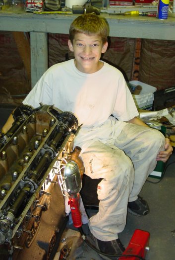 enough of a difference that additional futzing was required. Believe me, it takes very little to make the reaction plate tighter than works well. Bill McKenna had to do the same, he reported, though he used a grinder to take off the excess powder coat and such. Aaron and I didn’t resort to that, but we did whack and bump a fair amount. I suspect that professionals might actually take better account of the coatings when they use the reaction plate to fit new floors. I didn’t think of that when we were installing the new floor panels.