What we’ve done since February (!) 2008
This one is for Dan.
Just under a year ago, I said I was looking for a double-groove crankshaft pulley. I published a humorous email exchange at the time, and I had resolved to get a new pulley from Classic Jaguar. Funny how time flies — I had no idea it’s been a year since that time until I fished around on my website for that link. People ask me how the car is coming, and I think how leisurely the pace has been, punctuated by flurries of great activity. I have taken Mike Moore’s advice, given a few years ago on the Jag-Lover’s forum, to do something every day, even if it only amounts to cleaning tools. Sometimes, I’ll have to admit, I have been content to gaze upon the car — as if looking constituted work.
At any rate, I did get my pulley from Classic Jaguar, but I got a used part — my preference actually. And Dan Mooney was gracious, since I didn’t need the accessory pulley and bolts that he offered on his used parts listings. Dan has always been gracious and supportive through the course of this restoration, and I have used the Classic Jaguar website a lot over the years to watch the pros at work. I like to think I’ve been able to take cues, at least, from what happens in the CJ workshops, but I don’t think my toolsets quite match. Neither does my talent, alas.
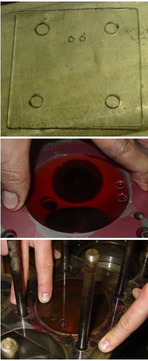
I went ahead a few weeks later to pick up a used low brake fluid level switch from CJ’s used parts collection. One of the two that came with the car broken too badly to repair; the other seems workable until I get around to replacing it or can figure out how to mend it. That is a challenge since the things were put together in a way that defies taking apart, and I ended up breaking both of them utterly when I was struggling to get the aluminum canister off. See the used replacement’s innards in the picture below.
Aaron has been involved with this restoration over all of the years, and he leaves to NASCAR Technical Institute in Mooresville, North Carolina, at the end of August. He told me that he wanted to get the engine running before he left, but it looks as though that’s probably not going to happen. We have gotten the major pieces in place, and in fact we have turned the engine over for a period to see the oil pressure pop up. (It went to 60 pounds in very little time, I’m happy to report.) Getting the ignition system straight has been a little bit of a challenge, mainly because I didn’t take the time to actually look at the distributor insides. I was expecting to hook the thing up like the original 3.8 liter engine, but the new engine has an electronic ignition, so the setup is significantly different at least at the distributor. (See the pictures below for comparisons of the original distributor and the newer one.)
The fuel pump is in place, but I haven’t connected the run of wire from the “rear” harness to the cockpit harness yet. (Remember, I modularized the wiring harnesses a bit more than they already were.) The fuel tank filler hose is in place, too. I had to buy one of those little pieces of rubber from a Jaguar vendor, because I couldn’t find a hose with the right inner dimension. Not even McMaster-Carr had something suitable. But I did some searching after I got the hose and could use the printed numbers on the rubber. Goodyear offers “Fuel Fill Hose SAE 30R6” in various inner dimensions. I believe an inner dimension of 2 1/4 inches would do the trick.
Various pictures collected over the months
The fuel level sensor. Essentially, it’s a rheostat. (Er, maybe a potentiometer, but I think not. The thing has two, not three, leads.) The whole thing is quite delicate, so if you go the route of cleaning it, be very careful. The brass float that dangles into the fuel drives the blade. There are two “switches” so to speak — one that signals the variable level (the rheostat) and the other that is on-off that signals low fuel. The lid that’s removed in this photograph plays a role in completing the circuits, too. When I opened this little box up, it was quite encrusted. Cleaned up pretty well, though.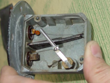
Looking down the XJ6 exhaust manifolds. I used the XJ6 manifolds that came with the engine I got from David Boger. Rather than heading straight down, the lower pipe slants backwards just slightly, and the manifold include a bolt-like bung hole plug. That plug makes it much too tight a fit against the left subframe, so I cut off the plug. The picture shows the front exhaust with plug and the rear exhaust with the plug cut off.I like the XJ6 manifolds for another reason: they include a heat shield setup that would seem to reflect heat downward. With all of the work on the paint, I really don’t want to have heat damage around the left louvres as I’ve heard some people have seen. Of course, the change in design means that the exhaust will have to be specially crafted, at least from the base of the manifolds to the front of the muffler section. I don’t think that will be too much of a challenge, though. 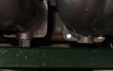
The engine compartment. Yes, please don’t pay attention to the mess. One of the thing I could do (but, apparently don’t) is take time to clean up the garage. It is shared, for the time being, with son Aaron, who also leaves his junk around. Working on my car includes quite frequently asking Aaron where tools are. But, aside from that, the engine compartment is coming together nicely, creating a sight that offsets some of the garbage in the background. Notably absent are the brake and clutch hydraulic fluid reservoirs and much else on that side of the engine. Since the time this photograph was taken (early July 2008), there has been some additional progress. A battery has been fitted, the heater fan assembly has been more firmly put in place, and a new starter solenoid (which still hasn’t worked right) is set up.You can see the oil cooler setup quite plainly, of course.
The rusty brake rotors need calipers fitted — and to be used — to get them clear of the red iron oxide. That, too, will come. 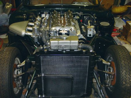
Lucas 22D distributor with condenser and points. This is the inside of the distributor that came with the 3.8 liter engine. It’s a Lucas 22D (note the marks) and it’s what I’m familiar with — mechanical and old fashioned with points and a condenser. I suppose I could use this one, as Glen Jarboe has on his 4.2 after he went through his engine rebuild. I’ll put this one aside, though, in favor of the distributor that came with the 4.2 replacement engine (below). If that one needs replacement, I might go with a Pertronix. 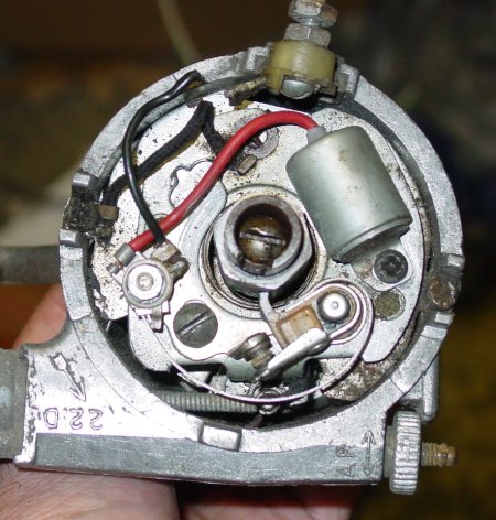
Lucas AB14 distributor with sensor. This distributor came with the engine I got from David Boger. People on the Jag-Lovers XJ6 forum seemed to think that this distributor is the Lucas AB14. It’s got a “CEI” (Something Electronic Ignition, probably) that has a sensor instead of the more mechanical approach that I’m familiar with. Peter Crespin, who knows a lot more than I do about these things, explained that the star-shaped center portion is a “normal six-point reluctor for the Hall effect pick-up coil at the side of the base plate.” This setup requires an amplifier, and David will be sending one to me. If the old electronic parts don’t pan out, I could install the mechanical 22D or put in a new Pertronix. My thanks go to Frank Anderson, Al McLean, Peter Crespin, David Boger and the Jag Lovers’ XJ6 forum.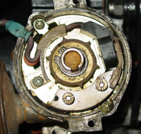
A handy mechanical oil pressure gauge under the bonnet. I’m not terribly impressed with the track record of the electronic oil pressure gauge. People seem to think that they’re maybe accurate to within 25% (and I believe that might be half in jest). With the two oil pressure sensor possibilities on the 4.2 liter engine I got, I went ahead and installed a mechanical gauge next to the windshield washer bottle and above the fuel filter bowl. The copper tubing goes to where the on/off pressure sensor used to be. I believe that the XJ6 had an oil pressure sensor there that was attached to an engine cutoff. The electronic sensor for the gauge was broken on this engine, and so I might attach the sensor from the 3.8 liter engine. It’s old, but it might work.Then, again, I might just stick a non-standard mechanical gauge in the cockpit. Lucas ones are available, I believe, though they display a different range of oil pressure than the electronic gauges do. Having an oil pressure gauge in the engine area is really nice. I’m considering installing a tachometer nearby, too. I believe they come in the two-inch form factor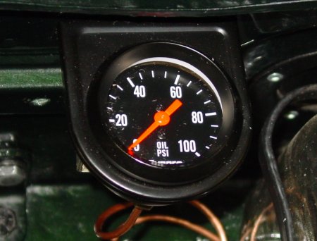
Insides of the brake fluid level switch. Both of my brake fluid level switches ended up being less than desirable. Both of them cracked when I tried to remove the aluminum canister that protects the cork float. One of them is more-or-less intact and still sits atop a fluid bottle, waiting until I replace it. The other broke into small pieces, and so I replaced it with a used part from Classic Jaguar. The replacement was really nice, and when I removed the aluminum canister, the top part came off. I took advantage of the inadvertent disassembly to clean and photograph it.The thing is dead simple. Simple enough that you’d think replacements would be cheaper. I just wish there was a way to replace the top cover and the canister without having to replace the whole part. The inset photo shows where the two contacts are hit by the metal disk that’s attached to the rod and float. One thing that might help others trying to replace a besotted cork: There is a hole near the top of the canister that is slightly pressed into the plastic of the assembly. If you take a knife and remove part of the aluminum that’s pressed into the hole, you might find removing the canister easier. It worked for me.