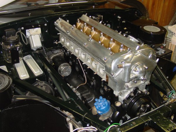
I wanted the engine to go in this fall, and it did! Aaron and I fiddled with the fit of the torsion bar reaction plate — the bane of the removal of the engine renewed in reverse! — and the next day slipped the engine into place. Here’s how it looked just after it was put into place.
The actual installation was on my birthday, so it was a very good day. As a matter of fact, I think it was my best birthday in years.
Aaron and I dropped the engine in from the top. Bill McKenna opted for the bottom, and there is some feeling that the bottom-up method is easier than dropping the whole hulk from the top. When we took out the engine the first week we had the car (over five years ago!), we lowered it and lifted the subframes to allow us to pull the engine and transmission forward. I recalled fighting with the motor mount brackets to get them to clear on the way down, so this time we put the engine in from the top. My father had warned about chipping the paint on the subframes, and so we put a couple of layers of masking tape on the frames. The tape did provide protection from the inevitable bumps.
It is a fairly tight fit from the top, and you do have the raise the engine high enough that it feels a little scary. The touchiest part is tipping the tranmission end down, though the hoist we have includes a nifty worm-geared adjustment that makes pitching the engine angle a matter of turning a crank. The process of setting the engine into place really amounted to easing it into place by gradual leveling of the engine and lowering it in steps. We did have some extra — perhaps even necessary? — wiggle room because we did not have the crankshaft pulley attached to the crankshaft dampner. (I actually haven’t bought it yet.) This meant we had a couple centimeters to play with when the oil pan was just below the top of the picture frame.
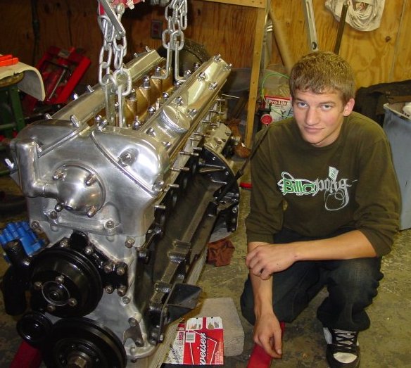
Not only has the engine changed…
It’s fair to say that the engine would still be sitting on the floor in front of the car were it not for Aaron, who worked to resolve some of the fitment issues that I had wrung my hands about over the past several weeks. Literally, I had fretted about things so much that I had avoided doing much to resolve the issues.
Well, I had actually fretted not so much about things in plural as a specific thing: that terror-inducing construct having to do with the torsion bars. As I’ve said before, I hate torsion bars. And our experience five years ago with the torsion bar reaction plate still is amazingly fresh in my mind. The thing was a beast to get off, especially since we were cramped under the car and hadn’t really too deep an understanding of the dynamics of the front suspension. The role of the reaction plate in the front still seems a little mysterious to me, since it has been claimed that the reaction plate actually imparts something between the two torsion bars, allowing them to communicate in some advanced engineering sort of way. Perhaps. All I know is that the plate goes in after the engine is in place, and the plate either fits or it doesn’t, since the fittings just won’t give.
To make sure that the reaction plate was going to fit, I actually used it to set the location of the two halves of the replacement floor (right and left), but that was before the POR-15, undercoating, primer, and paint. The coatings made enough of a difference that additional futzing was required. Believe me, it takes very little to make the reaction plate tighter than works well. Bill McKenna had to do the same, he reported, though he used a grinder to take off the excess powder coat and such. Aaron and I didn’t resort to that, but we did whack and bump a fair amount. I suspect that professionals might actually take better account of the coatings when they use the reaction plate to fit new floors. I didn’t think of that when we were installing the new floor panels.
It’s important to get all of the bolts fitted without having to contend with the engine and transmission, so if you’re doing a restoration like mine, fit the reaction plate before dropping the engine in. That little extra time will take hours off the work.
We took the tension off the torsion bars, of course. It actually isn’t that bad a job to do, but it is a hassle — seems too much a sideline in relation to the real show of the engine going in. And, of course, there’s no graceful way to get at the bolts for the torsion bars and the reaction plate once the engine is occupying all that space.
I was struck at how much Aaron has changed from the time when we first took the engine out (and he had managed to mangle a bronze bolt or two) and the time when we put the new engine in. Pictures say it all. He’s grown up to be a handsome man.
I’m now beginning to collect the parts I need to do all of the cooling and fuel and ignition work. Cooling hoses are the first thing on the list. I’ve found that bringing the old hoses into the parts shop works just fine. Gates replacement hoses are available, and Mike Frank has published a list of them. I’ll add to the options with another list in the near future. Several of the old hoses are either Jaguar replacements or (heaven forbid!) the originals. They’re in pretty tough shape.
The front suspension waited since the basic installation of the bearings, brake rotors, and wheel hubs. I hadn’t done much of anything to the torsion bars, since the prospect of actually setting them up just exhausted me. But with work proceeding on the steering column and the rack and pinion setup, I decided it was time to do the front suspension pieces a bit more permanently. This entailed setting the torsion bars (Oh, joy!) and putting the steering rack and tie rod assembly into place. I also fitted the shock absorbers. So, the only part that is not in place yet is the brake assembly. I figured that I would hold off on the front brakes until I can see the status of the rear brakes, which accept the Dunlop brake slave cylinders, as I understand it. (Classic Jaguar frequently fits the front brakes on the rear and then replaces the fronts with higher grade brakes.) That way, I should be able to get the rear suspension done and installed before I have to make a decision on the front brakes. If I fit the front brakes on the rear, I can also avoid doing a lot more nickle plating right away, though of course there are parts in the rear that will require plating. At this point I might just do the plating in one fell swoop in any case — it’s not an important decision at this point.
Adjusting the torsion bars was not as bad as I had anticipated, though it wasn’t a piece of cake either. The key at this point is to bring the tension on the bars to zero, so that means loosening the upper ball joint pin and not having any of the other tension-causing connections in place either. The steering tie rod end should not be connected nor should the anti-roll bar linkage. Of course, the shock absorber needs to be out entirely. In order to make sure that the upright isn’t damaged by flopping freely, secure it by tying up or otherwise securing the upright through the upper ball joint pin hole. I just used some old brake line and loosely attached the upright to the upper fulcrum shaft. You just need to have the upright and the lower wishbone swing freely enough to lower the wishbone to the required level. The required length according to the Bentley manual is 17 13/16 inches from the centers of the upper and lower bolts for the shock absorber. The manual supplies the plans for a bracket to hold the lower wishbone in place while adjusting the torsion bars.
The work is in the putzing that the torsion bar requires to fit correctly. I suppose there is a methodical way of doing it, but fine adjustment requires playing around with the fit on both ends of the bar, since there are a different number of teeth on each end (24 and 25). This difference makes it possible to do some fine tuning of the fit. It took me about a half dozen tries on both bars to get the holes to line up on the rear mounting brackets. If you’ve done the filing and fitting well enough on the teeth, you shouldn’t have to do much more than slide or perhaps gently tap the bars into place. I do think that the anti-seize grease is a good idea to use on those splines.
After the torsion bar is secure, you can begin putting pressure back onto the bar by attaching the various parts: anti-roll bar linkage, steering tie rod end, upper ball joint pin, and the shock absorber. I saved the shock absorber for the end, since it was easiest to attach the parts that had the greatest flexibility first. I used a small hydraulic jack under the lower wishbone to push the assembly upward in order to get the parts attached. Even with the other parts in place, I had to sit on the frame in order to install the shock. By the way, you need to attach the lower end of the shock absorber first, and then pull it up to fit the upper end.
As you can see, I have gone with “Boge” shocks all around. They have the same shape as the original Girling shocks, and they get good reports from people who have fitted them in a “stock” setup like what I have intended with this restoration. I suppose that if I wanted to look more “authentic” I could go ahead and paint these shocks the original Girling blue and they could pass for the old Girlings. Boge black suits me just fine, at any rate.
Fitting the shock absorbers did teach me the uses of being a part pack rat during disassembly. A small spacer that fits inside the bush-halves at the low end of the shock looked to me to be the kind of thing that many people probably toss. The piece looks like it might come shipped as part of replacement bushes, but that’s not the case. The part fits easily into the bushes, which you slide in at both sides of the shock. There is no need to press the spacer into place. The big end goes against the lower wishbone.
The heading says “front suspension,” but for all practical purposes it should read “torsion bars are the key — and the pain.” I have a vague suspicion that a great number of
restorations go swimmingly until torsion bars need to be dealt with. At that point, the would-be restorer throws up his hands in defeat and carts the car to a professional, or the garage becomes as silent as a crypt.
Like it or not, torsion bars and the parts that meet them make up a lot of doing the front suspension. As I found out, if you don’t prepare these parts before you assemble, you end up breaking things down and rebuilding. The truly bad thing about the torsion bars is that you’ll have to mess with them quite late in the game — when you have everything together and need to adjust them.
The shop manual I use has useful exploded views of many of the assemblies on the Jag, but it struck me as odd that the exploded view of the front suspension was spotty about the location of nuts and washers. The ball pins, for example, seemed to float freely without a washer or a means of affixing them to the assembly. I was thankful for my scrupulous photography during the breakdown of the car. Since the suspension was literally doubled — left and right sides — I could usually find a shot that showed what I needed.
I was fortunate enough to lurk on Jag Lovers E-type forum (http://forums.jag-lovers.org/) to read through active discussions of front suspension issues, and especially torsion bar installation. That helped greatly, though I didn’t find an opportunity to pose any questions. They were, for all practical purposes, already addressed by the assembled wise guys. Or my questions resolved themselves with some careful looking.
Perhaps you won’t make the mistakes I did.
— The Process, Distilled from Experience in the Garage —
The prepared lower wishbone assembly should look like this. When you are ready to install the brackets, tighten the nuts on each end so that the brackets fit snugly against the fulcrum shaft and the attached levers. This seems necessary in order to get the brackets to slide into their slots on the subframes.
This more or less distills the process of how I installed the front suspension. I have illustrated the text in the sidebar. This process comes after installing the front suspension (or at least one side of it) not once but twice. I managed to make enough mistakes to warrant dismantling my work and starting over. Overall, the key is to make sure you understand the subtle differences between the parts on the lower wishbone assembly. (Yes, the forged front wishbone levers do fit only on one side in spite of their seeming identity.) And the other big point is preparing the splines on the torsion bars and their splined fittings. Remember, you will be revisiting the torsion bars later when it comes time to adjust them. Later, of course, means after you’ve already got most everything else installed — and therefore haven’t much room left to fuss over the bars.Actually, I dread the thought of adjusting torsion bars later on down the road.Oh, and in all of this please note that “your mileage may vary” — use this narrative and the pictures to guide and inform your better judgment.
Assemble the upper and lower wishbone assemblies.
There are a couple of tricks with the parts making up the lower wishbone assembly. First, the ends of the fulcrum shaft are not equal; the front end is slightly shorter — by about 8 or 9 millimeters. Second (and this is not immediately apparent), the forged levers that attach to the “upright” via the ball pins fit on a specific side of the car. On the end where the splines for fitting the torsion bar, there is about a 2 or 3 millimeter indentation that extends over the hole with the splines all the way to the end of the piece. The indentation should face forward. I didn’t see any other indication for right and left.
This means inserting the fulcrum shafts and loosely attaching the brackets with their bushings already inserted. For the upper assembly, you can loosely fit just the bush and bracket part of the front bracket. That bracket has two parts, one of which you attach to the picture frame separately. Both front and rear brackets need to be loosely fitted onto the lower wishbone. I had mistakenly assumed that I could attach the lower bracket on the picture frame (the largest of the front suspension brackets) and then slide the fulcrum shaft into place. I found out this is either impossible or, if not impossible, hard to do without chipping away at paint and otherwise furiously banging.
Lower wishbone assembly.
The lower wishbone goes together quite easily. Mind the washers, especially those that sit between the bush and the castellated nuts. These are very close to the size of the washers that fit the upper wishbone assembly. Closer inspection shows that the hole for the lower wishbone washers is slightly larger than the washers fitting the upper wishbone. I had to scare up one of the special washers from Stefan Roundy, who called them “distance washers.” I was missing one for the upper wishbone and another for the lower. These are quite thick and they sit on the side of the bush opposite the castellated nut. The lower wishbone, as far as I can tell, has only one of these washers, located at the rear end of the fulcrum shaft. The front lever of the assembly — the part to which the torsion bar attaches — apparently doesn’t have a washer between the bush and the cast wishbone part, which is quite wide and flat on the side facing the bush in any case.
The fulcrum shaft for the lower wishbone is not symmetrical. One end has a longer section for fitting the wishbone part and the bush than the other, by a few millimeters. The longer of the two ends goes to the rear.
Although the “rear wishbone lever” (the tapered bar extending from the rear of the fulcrum shaft to the front lever) is for all practical purposes identical on both sides of the car, the “front wishbone lever” is specific to a side of the car. The difference is at the end with the splined hole that receives the torsion bar splines. The front-facing side of the bar is machined to be slightly indented. If you put the lower wishbone lever on the wrong side of the car, the lever will bang against the subframe, and probably cause damage.
At this point you actually begin preparing for the torsion bar installation. Using a triangular file (get a new one so it’s sharp), clean out the splines on the lower wishbone levers, inside the fitting that goes on the rear end of the torsion bars, and on the front and back ends of the torsion bars. This is tedious but it made all the difference for me, and I believe it will pay off in future adjustments. I didn’t do the cleaning for the first installation of the front suspension, and I found that the torsion bar installation was simply too difficult. I could get them in place, but the thought of having to adjust them was a nightmare. I figured I’d break everything on the lower wishbones down and start over. (Jag Lover’s was helpful here, since discussion of torsion bar adjustment was active at the time.)
File the fittings and the bars until you can place the bars into the splined holes without having to use anything more violent than a rubber mallet. You do not want to do too much filing so that the bars fit sloppily. They should be snug, but adjustable.
Upper wishbone assembly.
Upper front bush and suspension bracket. This piece attaches to the picture frame, and the bush and bracket attach to it with three bolts.
The front mounting bracket for the upper wishbone has two main parts, one that attaches by three bolts to the picture frame and the other that holds the bush. These two parts are attached by means of three 5/16 24 NF grade 8 bolts. Shims may or may not sit between these parts.
The rear mounting bracket fits directly to the side frame with two bolts and nuts. On the inside of the frame, where you attach the nuts, there is a stiffener sitting between the nuts and the frame. This bracket might also have shims. You can tell the difference between the stiffener and the shims by noting their shape. At least on my car, the stiffener had squared corners and was noticably thicker gauge than the shims. The shims had rounded corners, were thinner metal (26 gauge, perhaps), and one of the holes for the bolt was in fact more of a open-sided slot, making a “C” shape. The shims, of course, fit between the frame and the bracket.
It is easiest to attach the rear bracket and bush and the piece that fits to the picture frame separately, since these parts are situated such that you can slide the remaining wishbone assembly into place. (This unlike the lower wishbone which needs to be slipped into the subframes with brackets already attached to the wishbone assembly.)
Upper rear bush and suspension bracket. This part can be installed onto the subframe and the fulcrum shaft can be slid into position without a problem. This bracket does not have any shims, though they may need to be fitted later.
Insert the fulcrum shaft into the wishbone by slightly loosening the adjustable holes on the wishbone (one of the holes is threaded). Do this by inserting a screwdriver into the groove and spreading the groove slightly. Make sure that your screwdriver doesn’t extend into the hole itself, since that can either obstruct the fulcrum shaft or even damage it as you are inserting it. The fulcrum shaft goes into the threaded hole first with the threaded section of the shaft going in last, of course. I found that applying a bit of grease to the threads was useful, though I was also careful not to smear grease on the shaft. You do need to exert some pressure to screw the shaft through the threads, and there is a period when you don’t have access to the notches on the shaft. Those notches are for using a wrench to turn the shaft for adjustment.
I brought the threads through the hole and didn’t pay much attention to how far. Fine tuning the geometry of the front suspension comes later.
Upper wishbone ball joint/pin installation.
The ball joint/pin fits into the top of the upper wishbone, with the pin extending down through the oval-shaped hole below the chamber that holds the ball-shaped end. The ball pin is held in place by a concave fitting pressed on the top of the ball and held in place by a spring. The spring is pressed by a disk covering the top of the ball pin chamber in the wishbone. The disk is held in
The kit and the upper wishbone. The shims are a bit different, perhaps because they are designed to fit on top of the cap instead of under it. The original shims had a smaller hole in the middle. The cap disk is the original, not a part of the kit.
place by a circlip or, also called an “internal retainer clip” or a “snap ring.” The pin part of the ball pin is threaded, and a rubber boot protects the pin and exposed sections of the ball recessed inside the wishbone. This boot is held in place with an external wire ring that wraps around the base of the rubber boot and presses it into a groove on the wishbone.
To begin, it’s best just to clean the ball pin chamber on the wishbone, especially the bore that will accept the circlip. This groove surrounding the upper part of the ball pin chamber has a tendency to get clogged with residues from plating, rust, and general grime. If you don’t get this clean before putting things together, it’s a little tougher to clean up without sliding everything apart.
Apply a small amount of grease either to the ball pin where the pin and the ball meet or to the inside portion of the oval hole at the base of the ball pin chamber in the wishbone itself. This should lubricate the lower section of the ball pin after it is placed into position. Then insert the ball pin into the chamber. The ball is pressed down by a short cylinder with one concave end. The concave space has a hole in the center of it. Grease the top of the ball pin or the inside of the concave surface, and place the concave surface into contact with the top of the ball pin. (My kit came with the concave fitting already coated with waxy grease, and I added some.)
The view of the upper part of the ball pin and the concave section of the fitting with grease smeared on it.
Place the spring on top of the concave fitting. Now comes the hard part. You need to press the cap down and insert the circlip. I used two small “Visegrip” welding clamps to hold the cap in place. I think the ideal would be to use a wheel puller-type tool to press the center of the cap, but I don’t have one … yet. I found that a key here was to make sure that the garage door is closed. I ended up losing a circlip because it flew right out the door and the only other one I had also sproinged into oblivion. As a matter of fact I had to order not one set of circlips, but two. I mismeasured and ordered the first set too large. They are 1 3/8-inch. (If you need some 11/2-inch circlips, let me know. I’ve got 25 of them.)
You can put the cap on anytime after you’ve installed the upper ball pin and associated parts. I installed the caps after I had fit the “uprights” and the torsion bars (basically everything else was done but the caps). I did that so that I could bear down on the cap. I can see that installing the caps before mounting the upright onto the upper and lower ball pins would make that installation easier. Once installed, the cap keeps the ball pin from spinning too freely, so it’s easier to get the lock nut on the pin.
The cap that came with the kit had a place for a grease fitting. That fitting was added for the Series 2, if I’m not mistaken. The original cap is slightly thicker than the replacement, and it has “A&A” stamped on it. The picture of the replacement cap that came with the kit includes the grease fitting and a shim. A nylon disk fits under the grease fitting to cover a small offset hole to release excess grease. The old shim I found during disassembly covered a larger area, sized as it was to the diameter of the cap but with a smaller hole in the center, perhaps 1/4inch wide.
The rubber boot goes on easily. Slip it over the pin that is now extending from the wishbone, and slip the wire retaining ring over it into the groove on the boot. I used a piston ring expander to expand the ring, though the tool probably wasn’t necessary.
The cap in place. I didn’t have to use shims.
Lower ball pin installation on the “upright”
Clean out the threads for the four bolts.
The lower ball pin fits into the bottom section of the so-called “upright” which is the part that connects upper and lower wishbones and accepts the stub axel and the brake caliper. It is slightly larger than the upper ball pin. The kit I used contained a steel alloy ring that fit into the large hole on the upright. It also contained a plastic retaining cup that really had no place to go in the assembly on my 1963 E-type. I assume it was used on other cars using the same type of ball pin setup. The installation process is similar to the installation of the upper ball pin, except it is perhaps a bit easier because the ball is held in place by a steel cap that is held in place by four bolts. You don’t need to fuss with a circlip.
Use a wooden tamper to avoid denting the surface of the alloy ring when you insert it. Notice the groove in the alloy ring to the left of the wooden tamper. This is not a flaw or damage. The groove allows the passage of grease to the upper section of the ball pin.
I cleaned up the threads for the bolts using a 5/16 24 NF tap and wire brushed the hole where the steel alloy ring was to go. I let the steel ring sit submerged in engine oil for a while before inserting it from the bottom of the upright. Using a small piece of hardwood as a soft “punch,” I tapped the ring into place without any problem. The ring should fit firmly. The ring should extend about three millimeters or so on the top side of the hole. There is a small groove surrounding the ring where the rubber boot fits.
Note the bendable bolt locking insert. (The zinc plated BEES bolts look good in spite of the fact that the picture is out of focus!)
Insertion of the ball pin is quite similar to the process used for the upper wishbone installation: you apply a small amount of grease and insert the ball pin. Noteworthy in the design of the steel ring is a small groove that extends in a curve inside the ring, on the face where the ball and the ring meet. When I first saw the groove I thought that perhaps I had received a damaged ring, but it turned out that the other kit had an identical groove. I then realized that the groove was an intentional design to allow grease to move from the lower section of the ball joint assembly — really where the grease fitting is — to the upper area of the assembly that is covered by the rubber boot.
Tin shims fit between the body of the upright and the conical cap. My kit included four thin shims and one slightly thicker one. I installed the shims one at a time, tightening the four bolts each time, until the ball pin was movable. One thing that got in the way of the cap installation resulted from the clear coating I had applied to the nickel plated parts. I had to sand off the coating so that the shims and the cap would sit true.
I used a piston ring expander to spread the wire retaining clip around the rubber boot.
When you have the correct number of shims in place, remove the bolts, place the bolt locking inserts, and reset the bolts. I didn’t bend the bolt locking inserts around the bolts (and won’t until everything is unambiguously correct). I put in a new grease fitting, too. It goes into the cap.
A small note: I was able to use the original BEES bolts on the cap, and only had to replace one of the bolts. I was particularly proud of my zinc plating job on those bolts. They really look quite good — too bad they’re placed where practically no one else in the world will be able to see them!
The last thing is the easiest. Slip the rubber boot over the pin that is extending from the upright now that it’s in place. Put the wire ring into the groove at the base of the boot. I used a piston ring expander to expand the wire, but this can probably be accomplished without a tool.
Joining the wishbones with the upright. This is, perhaps, the easiest of the tasks (and because of that, I’ve not illustrated this section with photographs). Basically the upright is attached by inserting the pins in the appropriate places. The upper pin in the wishbone goes into the hole at the top of the upright, and the lower wishbone has a hole into which the lower ball pin fits from below. The kits I used include new nuts with nylon “locks.” I found that the nuts went on nicely until the nylon hit the threads, and then the pins had a tendency to spin. Since the pins are (mostly) held in place by friction, I used my rubber mallet to tap the wishbones, thereby setting the pins more tightly into place. This firmed up the pins so that it was quite easy to tighten the bolts. By the way, there are washers for every bolt on these pins. My lower ball pin kits didn’t include new ones (the originals are quite thick); the upper ball pin kits included new washers.
A note on greasing the ball pins. I chose not to shoot grease into the upper and lower ball pins until after I had completely finished the assemblies. I did this because I wanted to be able to remove the upper and lower ball pins more easily if I needed to, and greasing them might have made removal more difficult because of spinning. I didn’t need to remove these again, but I think holding off on the grease is prudent. You just need to remember to grease before you do any sort of serious movement of the suspension.
Torsion bars. I have to admit, torsion bars are not my favorite things in the world.
Although the torsion bars are mechanically interchangable, they are intended to fit on a specific side of the car. They are labelled on the front end with an “RH” (right) or “LH” (left). Installing the torsion bars on the wrong side may make them fail, so don’t do it.
The torsion bars are labelled for right and left. You’ll see “R H” and “L H” on the front end of the torsion bar (the end with the groove crossing the middle of the splines). Although the right and left bars will indeed fit on either side, switching them may invite failure of the bars, so put the “R H” on the right and “L H” on the left. I believe this has something to do with the way that steel adapts to tension — as long as it is consistent, the steel holds, but wrenching the torque the opposite way (as when you put the right on the left, and vice versa) weakens the steel.
The key is to make sure that the splines on both ends are clean and rust free. They should slip into their receivers on the wishbone and on the rear bracket without too much whacking. As a matter of fact, being able to slip the torsion bar splines into these parts without a rubber mallet is desirable. But you do not want to make the match “sloppy.” I learned in getting my torsion bars ready that if you drop a bar on a cement floor, you can expect the splines to have been altered slightly enough to make refitting into a wishbone or bracket more difficult (though not impossible, thank goodness). The moral: If you drop it, check it. Also, any amount of whacking with a steel hammer is likely to change things, so use a rubber mallet whenever possible. If you must use steel to hammer, find the indentation on the end of the bar, insert a punch into it, and then “drift” the torsion bar back and forth into place.
The wishbone splines should look like this: clean and sharp. Note that the wishbone lever is recessed slightly over the opening for the splines. This recess needs to be orientedtoward the front or else the lever will not swing freely over the frame above it. Instead it will smash into the frame at that point and cause damage. The rectangular groove inside the hole is where the retaining bolt emerges to fit into the groove in the center of the front splines on the torsion bar.
Use a triangular file to clean up the splines on the bar and in the receivers on the wishbone part and the rear bracket. Insert the torsion bar frequently to test the fit, and be sure to rotate the bar in the parts, since you’ll be adjusting the tension of the bar by rotating the bar. It needs to fit any number of positions, not just one. A note on adjustment: the torsion bars can be adjusted very finely, it turns out, since both the rear and front splines can be set. There are 25 rear splines and 24 in front, making the adjustment possible to a tiny degree. Besides, you can’t accidentally insert the rear splines into the wishbone receiver — unless, of course, you really mess up the splines.
Before inserting the torsion bars apply an anti-seize grease to the splines. The stuff is like sticky mud with a brown coppery color. It’s also supposed to keep the meeting surfaces free, which is important since the torsion bars will need adjustment at least once more before the car is back on the road.
When you’re ready to put the torsion bars into place, fit the rear fittings onto the bars, so that they swing loosely around the bar in front of the rear splines. Then insert the rear splines into the large hole on the frame where the torsion bar fitting rests and move the front part of the torsion bar into place in the splined hole on the lower wishbone lever. I found that I could gently rest the bars in place without completely inserting them before putting some grease on the splines and the holes.
The Jag Lovers E-type forum mentioned the use of “anti-seize” grease for the torsion bars, and I decided this was the way to go. I have used a regular old lithium grease, but I believe I’m going to move toward a “multi-purpose” grease in the future. The anti-seize formulas include metals, and the one I got was based on copper, which I gather is common among anti-seize products. My guess is that one brand is as good as another. I applied the anti-seize grease to both the torsion bar ends and the fittings they were to go into. It’s quite messy stuff — as thick as glue or river-bottom mud. The bottle I got had a brush in the cap for applying the stuff.
After all of the Sturm und Drang of the first time I had installed a torsion bar without the preliminaries of filing and cleaning and fitting, the torsion bars went on neatly and quickly. I installed both bars in less than fifteen minutes, using only a rubber mallet for “convincing” — gentle at that!
The torsion bars fit nicely, without too much work. I used a rubber mallet to tap them into place from the rear, and then after the front fitting was secure, I moved the rear fittings into place. I have put a couple of bolts into the rear fittings just to hold them in place. The set up by no means is able to hold much weight, but that’s not a concern right now. I plan on finding my torsion bar reaction plate and putting it in place. I haven’t seen that part since I installed the new floors some time ago. I want to make sure that the reaction plate is in good shape with the new torsion bar set up. After that is checked out, I can remove the reaction plate for more permanent installation after the engine is in place.
I remember that getting the reaction plate out was an ordeal. I hope putting it in isn’t — though I have a feeling it will be a job that is joyful only after it’s complete.
I’ll return to the front suspension later, when I’ll take on fitting the stub axels, brake calipers, steering couplings, and all the rest. I figure this will take a while.
It would be nice to have a “rotisserie” to mount the car body on. Such things are do-able, and I’ve seen them around, but I’ve not wanted to invest the time into building such a fancy rotating mount for the car. I suppose it would be nice, but we’ll flip this car over as need be. That said, I did need to create something to make it easier to move the body out of the way when we weren’t going to be working on it. I used lumber we had saved from an old chicken coop and four middle duty casters from the lumber yard to build a rolling rack. It stands about two feet high, and it carries the car quite high — perhaps a little too high. But it’ll do. And it was really nice to be able to roll the car body to the side to sweep the floor and clean up. It’ll practically be necessary once we need to move larger parts (like the bonnet) out of the garage to work on. The fact that it’s fairly high is also a nice feature, since I won’t have to be bending down all of the time to work on areas in the interior.
Aaron and I continued to disassemble the tubular steel frame, especially the right side suspension and frame pieces. We got everything apart, except for the lower wishbone and the torsion bar. these are still stubbornly affixed to the frame. The wishbone is free, but it is held to the frame by the torsion bar. I suspect that we’re either missing a piece to remove or the thing is just plain stuck. We ran into some difficulty removing a couple of the larger bolts, and we had to resort to heating up the nut after penetrating fluid failed to loosen things up. Heat worked like a charm. Thank goodness we have a pneumatic impact wrench!
Very Evil Rust (16 March 2003)
We did run into something I had dreaded, however.
I was thinking that the tubular steel frame was untouched by rust, but that proved not to be the case. When Aaron and I flipped over the frame assembly in order to get at some bolts more easily, we found two badly corroded areas on the left frame. One section near the picture frame (the central section the runs across the front, spanning the gap between the two side frames) was rusted through on the bottom. And a section below the battery area, on the underside of the tube, was rusted clear through. This damage wasn’t apparent from the top of the vehicle, though when everything was flipped over it was very easy to see.
I was hoping that I could avoid buying a new frame, since the things are pricey. But there is no way that I would attempt fixing this part. There is too much quite literally riding on it to test my skills. The tubular steel was also a very high tensile strength, and I simply do not have the tools to do the job. I think that the side frames cost around $ 750, and I should be needing to get one. The right side frame looks very good. I’ll know more about it after sandblasting it. I’m almost afraid to see what lies under the old paint.
 The tape did provide protection from the inevitable bumps.
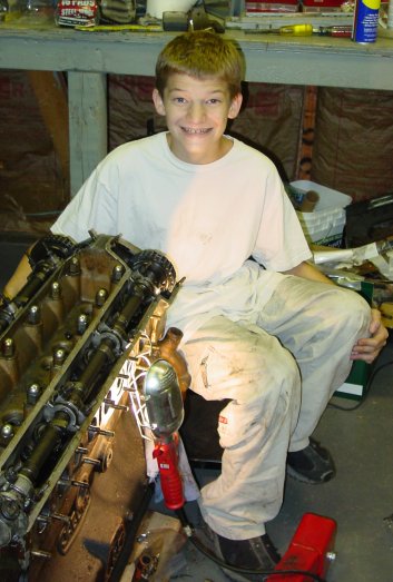 enough of a difference that additional futzing was required. Believe me, it takes very little to make the reaction plate tighter than works well. Bill McKenna had to do the same, he reported, though he used a grinder to take off the excess powder coat and such. Aaron and I didn’t resort to that, but we did whack and bump a fair amount. I suspect that professionals might actually take better account of the coatings when they use the reaction plate to fit new floors. I didn’t think of that when we were installing the new floor panels.
 building such a fancy rotating mount for the car. I suppose it would be nice, but we’ll flip this car over as need be. That said, I did need to create something to make it easier to move the body out of the way when we weren’t going to be working on it. I used lumber we had saved from an old chicken coop and four middle duty casters from the lumber yard to build a rolling rack. It stands about two feet high, and it carries the car quite high — perhaps a little too high. But it’ll do. And it was really nice to be able to roll the car body to the side to sweep the floor and clean up. It’ll practically be necessary once we need to move larger parts (like the bonnet) out of the garage to work on. The fact that it’s fairly high is also a nice feature, since I won’t have to be bending down all of the time to work on areas in the interior.
 spanning the gap between the two side frames) was rusted through on the bottom. And a section below the battery area, on the underside of the tube, was rusted clear through. This damage wasn’t apparent from the top of the vehicle, though when everything was flipped over it was very easy to see.