Front suspension
The front suspension waited since the basic installation of the bearings, brake rotors, and wheel hubs. I hadn’t done much of anything to the torsion bars, since the prospect of actually setting them up just exhausted me. But with work proceeding on the steering column and the rack and pinion setup, I decided it was time to do the front suspension 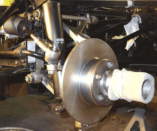 pieces a bit more permanently. This entailed setting the torsion bars (Oh, joy!) and putting the steering rack and tie rod assembly into place. I also fitted the shock absorbers. So, the only part that is not in place yet is the brake assembly. I figured that I would hold off on the front brakes until I can see the status of the rear brakes, which accept the Dunlop brake slave cylinders, as I understand it. (Classic Jaguar frequently fits the front brakes on the rear and then replaces the fronts with higher grade brakes.) That way, I should be able to get the rear suspension done and installed before I have to make a decision on the front brakes. If I fit the front brakes on the rear, I can also avoid doing a lot more nickle plating right away, though of course there are parts in the rear that will require plating. At this point I might just do the plating in one fell swoop in any case — it’s not an important decision at this point.
Adjusting the torsion bars was not as bad as I had anticipated, though it wasn’t a piece of cake either. The key at this point is to bring the tension on the bars to zero, so that means loosening the upper ball joint pin and not having any of the other tension-causing connections in place either. The steering tie rod end should not be connected nor should the anti-roll bar linkage. Of course, the shock absorber needs to be out entirely. In order to make sure that the upright isn’t damaged by flopping freely, secure it by tying up or otherwise securing the upright through the upper ball joint pin hole. I just used some old brake line and loosely attached the upright to the upper fulcrum shaft. You just need to have the upright and the lower wishbone swing freely enough to lower the wishbone to the required level. The required length according to the Bentley manual is 17 13/16 inches from the centers of the upper and lower bolts for the shock absorber. The manual supplies the plans for a bracket to hold the lower wishbone in place while adjusting the torsion bars.
The work is in the putzing that the torsion bar requires to fit correctly. I suppose there is a methodical way of doing it, but fine adjustment requires playing around with the fit on both ends of the bar, since there are a different number of teeth on each end (24 and 25). This difference makes it possible to do some fine tuning of the fit. It took me about a half dozen tries on both bars to get the holes to line up on the rear mounting brackets. If you’ve done the filing and fitting well enough on the teeth, you shouldn’t have to do much more than slide or perhaps gently tap the bars into place. I do think that the anti-seize grease is a good idea to use on those splines.
After the torsion bar is secure, you can begin putting pressure back onto the bar by attaching the various parts: anti-roll bar linkage, steering tie rod end, upper ball joint pin, and the shock absorber. I saved the shock absorber for the end, since it was easiest to attach the parts that had the greatest flexibility first. I used a small hydraulic jack under the lower wishbone to push the assembly upward in order to get the parts attached. Even with the other parts in place, I had to sit on the frame in order to install the shock. By 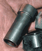 the way, you need to attach the lower end of the shock absorber first, and then pull it up to fit the upper end.
As you can see, I have gone with “Boge” shocks all around. They have the same shape as the original Girling shocks, and they get good reports from people who have fitted them in a “stock” setup like what I have intended with this restoration. I suppose that if I wanted to look more “authentic” I could go ahead and paint these shocks the original Girling blue and they could pass for the old Girlings. Boge black suits me just fine, at any rate.
Fitting the shock absorbers did teach me the uses of being a part pack rat during disassembly. A small spacer that fits inside the bush-halves at the low end of the shock looked to me to be the kind of thing that many people probably toss. The piece looks like it might come shipped as part of replacement bushes, but that’s not the case. The part fits easily into the bushes, which you slide in at both sides of the shock. There is no need to press the spacer into place. The big end goes against the lower wishbone.
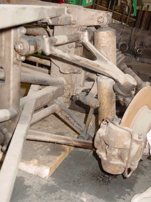 the front suspension and steering mechanisms intact. The entire structure needs to be completely taken apart so that the steering, the suspension assemblies and the three-part frame itself can be thoroughly cleaned and, as the case may be, renewed.
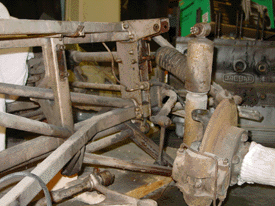 I had to remove the upper shock absorber fastener in order to gain access to it. This fitting had three very stubborn bolts that took a great deal of penetrating fluid and many taps on the wrench to remove. I was careful not to be too free with my hammer, since replacing these pieces could be a real challenge. All the hardware is grade 8, however. And so, it is quite tough. The bolts themselves look untouched by the forty-some years they’ve sat. I’m guessing the a coating of paint may just have given them some extra life.
 floor sealed by the end of the week.