Engine mounted on stand
We went to a local auto parts shop and bought an engine stand. I had looked around and I thought they were much more expensive  and was delighted that we could walk away with ours for under $40 USD. We hadn’t really explored the engine — like the removal of the oil pan to inspect the crankcase area — and the engine stand made this much more possible. Most engine stands connect to the engine by the bolts used to attach the bell housing at the rear end of the engine block. (I’m not sure exactly how new-fangled sideways engines are attached to their engine mounts. I assume that there is a wholly different breed of engine stands for such engines.)
In order to fit the engine onto the engine stand, we had to remove the clutch assembly and the flywheel. These two parts are supposed to be marked when they are balanced, but we were unable to find the balance marks. The clutch and the drive plate were in pretty good shape. The clutch had a little wear, but it was still in servicable condition when the car was put into storage. Of course, we’ll fit a new clutch. The drive plate is smooth and not pitted at by rust. It just needs a good cleaning. To remove the flywheel we were thankful to have had a pneumatic impact wrench. The ten bolts were pretty tight, though not fused with rust. They are very closely seated, so getting the socket around the bolts was a bit challenging. Everything came off nicely after a little tapping.
Oil pan removed, thrust washers found loose
When we took off the oil pan, we searched for any extra parts that might have worn off. We found the thrust washers loose in the crankcase area. They probably fell out some time ago.  At this point we have not investigated the damage that may (or, we hope, may have not) been caused by the lack of thrust washers. They were a bit of a mystery at first, since they obviously were not crankshaft bearings and they gave the impression of being halves of a single large washer that was split. The thrust washers fit on both sides of the middle crankshaft support. I think they stabilize the crankshaft from forward and backward movement, though I don’t know how critical they are, since it would seem to me that most of the strain on the crankshaft would be vertical and horizontal — coming from the up and down motion of the pistons. A cursory look at the middle support and the surrounding fittings revealed no apparent damage. We’ll need to see about the wear in this area, just to see if the section is so large that the thrust washers won’t fit snugly.
One of the thrust washers was a bit bent on one end, and there was some shearing at one end. It probably slipped out and was bent and pinched on its way out. After the first one came out, the other one was probably much looser and more or less fell out intact. These pieces are supposed to be marked if they are oversized, and I didn’t see any markings to that effect. (I didn’t look closely, I have to admit.) These pieces may not have been correctly reinstalled.
Oil pan and pan baffles cleaned and reassembled
The amount of sludge on the bottom of the oil pan was less than what I’ve seen on other engines, making me think that the last overhaul of this engine wasn’t that long ago. We scrubbed the aluminum oil pan after removing the baffles. A bit of wiping, rinsing with kerosene, and some scrubbing with liquid laundry detergent got it nice a shiny. The baffle was a little more permeated with oil and dirt and so it didn’t come out quite as clean. We removed all the sludge, though, and reassembled the pieces. It is a nice clean job now.
 |
 |
The pictures show the top and bottom views of the oil baffle. The purpose of the individual box-like compartments isn’t really clear to me. The oil pump sump fits at the center of the piece, in the round screen bowl.
Piston heads cleaned, markings revealed
We used steel wool, kerosene and elbow grease to remove carbon deposits that were mainly on the exhaust port side of the piston heads.  I suppose this wasn’t really necessary at this point, but it can do nothing but good to remove some of the collected grit from the cylinders and pistons. This cleaning had the benefit of allowing us to see markings on the pistons that show that these pistons are oversized by 0.030 of an inch. That is the largest size that Jaguar recommends before resleeving the cylinders and resizing the pistons to their initial measurements. The markings also confirm absolutely that the engine has been overhauled (not an unusual thing, of course — it would be far more unusual to find an engine of this vintage that had not been overhauled).
The pistons themselves look pretty good. They are good solid circles, no blowouts or weird tapers. I figure that we’ll pull each one out, one at  a time, to replace the rings and bearings. Then after one is back in place, we’ll remove the next one, and so on. This, of course depends on whether we’ll need to remove the crankshaft to do whatever needs to be done about the thrust washers. At this point, however, I’m thinking that the issue with the thrust washers was a matter of incorrect installation or perhaps a misfit of part. As a matter of fact, it’s not clear to me that the thrust washers were in fact replaced at the last overhaul. The ones that were mangled may indeed have been the originals. I don’t know yet.
We’ll need to get a tool to remove the rings, I suppose. I can’t recall what my dad and I used to remove rings, unless we simply used plyers and didn’t worry about damaging them. I do recall using cut Campbell Soup cans to compress the rings around the pistons to reinstall them. That was long ago, though, and on a Mustang that was about two years younger than this old Jag.
Good memories — and ones that I hope might be passed to the next generation.
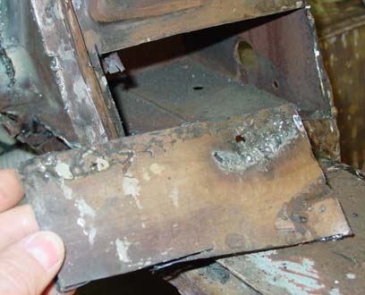 the outside of the “B”-pillar actually had some structural impact. Unfortunately, the way to obscure the fix was to apply bondo, and so the structural repair was apparent in a large lump of bondo about five centimeters from the base of the pillar, just under the door striker.
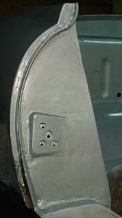 Then we measured the hole carefully, cut it out, and welded it into place. The tabs themselves were spot welded, and then along the perimeter we used a regular old butt weld.