The front suspension waited since the basic installation of the bearings, brake rotors, and wheel hubs. I hadn’t done much of anything to the torsion bars, since the prospect of actually setting them up just exhausted me. But with work proceeding on the steering column and the rack and pinion setup, I decided it was time to do the front suspension pieces a bit more permanently. This entailed setting the torsion bars (Oh, joy!) and putting the steering rack and tie rod assembly into place. I also fitted the shock absorbers. So, the only part that is not in place yet is the brake assembly. I figured that I would hold off on the front brakes until I can see the status of the rear brakes, which accept the Dunlop brake slave cylinders, as I understand it. (Classic Jaguar frequently fits the front brakes on the rear and then replaces the fronts with higher grade brakes.) That way, I should be able to get the rear suspension done and installed before I have to make a decision on the front brakes. If I fit the front brakes on the rear, I can also avoid doing a lot more nickle plating right away, though of course there are parts in the rear that will require plating. At this point I might just do the plating in one fell swoop in any case — it’s not an important decision at this point.
Adjusting the torsion bars was not as bad as I had anticipated, though it wasn’t a piece of cake either. The key at this point is to bring the tension on the bars to zero, so that means loosening the upper ball joint pin and not having any of the other tension-causing connections in place either. The steering tie rod end should not be connected nor should the anti-roll bar linkage. Of course, the shock absorber needs to be out entirely. In order to make sure that the upright isn’t damaged by flopping freely, secure it by tying up or otherwise securing the upright through the upper ball joint pin hole. I just used some old brake line and loosely attached the upright to the upper fulcrum shaft. You just need to have the upright and the lower wishbone swing freely enough to lower the wishbone to the required level. The required length according to the Bentley manual is 17 13/16 inches from the centers of the upper and lower bolts for the shock absorber. The manual supplies the plans for a bracket to hold the lower wishbone in place while adjusting the torsion bars.
The work is in the putzing that the torsion bar requires to fit correctly. I suppose there is a methodical way of doing it, but fine adjustment requires playing around with the fit on both ends of the bar, since there are a different number of teeth on each end (24 and 25). This difference makes it possible to do some fine tuning of the fit. It took me about a half dozen tries on both bars to get the holes to line up on the rear mounting brackets. If you’ve done the filing and fitting well enough on the teeth, you shouldn’t have to do much more than slide or perhaps gently tap the bars into place. I do think that the anti-seize grease is a good idea to use on those splines.
After the torsion bar is secure, you can begin putting pressure back onto the bar by attaching the various parts: anti-roll bar linkage, steering tie rod end, upper ball joint pin, and the shock absorber. I saved the shock absorber for the end, since it was easiest to attach the parts that had the greatest flexibility first. I used a small hydraulic jack under the lower wishbone to push the assembly upward in order to get the parts attached. Even with the other parts in place, I had to sit on the frame in order to install the shock. By the way, you need to attach the lower end of the shock absorber first, and then pull it up to fit the upper end.
As you can see, I have gone with “Boge” shocks all around. They have the same shape as the original Girling shocks, and they get good reports from people who have fitted them in a “stock” setup like what I have intended with this restoration. I suppose that if I wanted to look more “authentic” I could go ahead and paint these shocks the original Girling blue and they could pass for the old Girlings. Boge black suits me just fine, at any rate.
Fitting the shock absorbers did teach me the uses of being a part pack rat during disassembly. A small spacer that fits inside the bush-halves at the low end of the shock looked to me to be the kind of thing that many people probably toss. The piece looks like it might come shipped as part of replacement bushes, but that’s not the case. The part fits easily into the bushes, which you slide in at both sides of the shock. There is no need to press the spacer into place. The big end goes against the lower wishbone.
This part of the front suspension story focuses on the wheel hubs, the bearings, and the brake rotors. Actually, the process is quite straightforward, and it is certainly easier than the installation of the wishbones. One thing that might look a little odd is that the hubs are both sporting “socks” — quite literally. The socks are there to protect the splines from damage. It’s a good thing to have on the hubs from the very first time that the hubs are exposed after removing the wheels. Hubs are very expensive little parts to replace, and damaged splines are a primary reason for replacement.
I believe the hubs on the E-type originally were plated, and there was evidence of plate (nickel?) on my hubs. I decided not to have them replated, since they are totally obscured by the wheels. In order to prevent rust, I am waxing the exposed steel and applying a “waxoyl”-like sealant. That, and the fact that the car is not going to do duty in bad weather, should keep the wheels in reasonably good shape.
The steering arm attaches to the central lock nut on the stub axel and to the upper forward support (one of four such supports radiating from the center of the upright).
Cleaning up the hubs was a chore. I had to sandblast the grime and fused rust-grease off. Then I polished the surface with a wire brush and coarse steel wool.
It’s important to install the correct hub on each side. Reverse them, and you might find that your front wheels won’t stay on. That is definitely a problem!
Here’s my experience. Take it as information from someone whose done the work. Remember “your mileage may vary” — use this narrative and the pictures to guide and inform your better judgment.
Install stub axel and the steering arm. The stub axel fits into the center hole in the upright. The steering arm fits between the upright and the stub axel nut and extends to the upper forward support, which is one of four such supports that radiate from the center hole. The rear pair are used to attach the brake caliper and the lower forward support is used to attach the brake line bracket.I found that all of the threads on all of these supports needed to be cleaned out, and now is the time to do the cleaning of all of the threads. If you wait to do the brake caliper threads until after you have installed the brake rotor, you will have a bit of trouble, since the rotor will get in the way. So, if you want to clean threads, clean them all before mounting anything on the supports. The threads on my uprights were 1/2 inch 20 NF threads.
The left side steering arm bears an embossed “R” that made me think it was supposed to go on the right. Apparently this is not the case, since the part only fits on the left side.
The four bolts that fit into the support holes are in three sizes. The two with holes drilled through the heads are for the brake calipers (the holes are for the wire lock), the longest one of the bunch is for the steering arm, and the shortest one is for the brake line bracket. All of the bolts should have split lock washers. I plated the bolts with zinc, as (I believe) they were originally.
I ran into a curious thing on one steering arm. The two arms are specific to a side, and they are not interchangable. Often the side is indicated on the part (as with the torsion bars), but I found that the steering arm that fit on the left side of the car has a raised “R” near the part number, and the steering arm on the right was unmarked. It could be that the “R” is actually unrelated to which side the part goes on, though it seemed an odd casting mark to use in this case. (The sidebar includes a photograph of the steering arm with the “R.”)
The stub axel gets firmly pressed into the recess on the outer side of the upright as you tighten the stud axel nut. The nut itself has a nylon lock ring. Inspect the nylon before fitting the stub axel with it. If the nylon has been damaged, it’s best to replace the nut. This nut, I would think, would have been a good candidate for something other than nylon to provide the locking.
Place the splash guard, rubber seal, and the inner bearings on stub axel. Now that the stub axel is in place, the process of fitting the various parts of the bearings begins. To put the bearings in, surprisingly enough, you practically don’t need any tools (except when setting the races and attaching the rotor) until the very end when you’re ready to set the hub into place and adjust the tightness of the hub against the bearings. You do need to get your hands greasy.
The inner bearing goes on the stub axel after you have put the stub axel splash guard (or “water deflector”) and rubber seal on. The rubber seal is a bit confusing to set into place — which side does the flat face go on? I tested the faces of the seal against the inner bearing and found that the flat face should go away from the bearing. The flat face of the rubber seal seemed to impede the freedom of the bearing, and besides, my recollection of the removal of the old seal had the flat face pointing away from the bearing. Before you put the bearing into position, liberally pack it with grease.
My bearing kits came with the rubber seal, the bearings and their races, a cotter key to lock the castellated nut, and a pillow-like tube of grease. The tube of grease was severely brittle, probably from long contact with the grease, and so it crumbled as I squeezed out grease to apply to the first parts I installed. The trouble was that I was afraid of introducing small bits of plastic into the bearings, so I threw the tube away and fetched a can of multi-purpose grease. My grease has a red color, as you’ll see in the pictures. I was able to reuse the splash guards (also known as “water deflectors”), even though these are frequently mangled when they’re removed. I replated them with zinc. There are two of these: one that fits around the inner end of the hub and the other that fits over the stub axel nearest the upright.
The order of installation over the stub axel is 1) the splash guard, 2) the rubber seal, and 3) the inner bearing. See the photograph for how the parts actually look when in place. Basically, the splash guard goes on the stub axel so that the concave sections of the ring will accept the hub-installed splash guard. (Yes, there are two splash guards that look quite different. One mounts on the stub axel, and the other goes on the hub.) The splash guard might fit in by pressing it firmly with your fingers. If not, a tap or two with a rubber mallet will do. The rubber seal fits easily with fingers. I was a little confused by how this seal was oriented at first. I tested it against the inner bearing, and I found that if you place the flat (more or less) side of the seal against the bearing, the bearing didn’t move freely. Putting the concave side against the bearing let the bearing spin freely. That concave side has a small spring fitted inside the ring — at least mine did. Grease the bearing well before slipping it on the stub axel. It will go on easily, though it’ll probably need to be well lined up. Making sure that the stub axel is clean will ease placement of the bearing. The bearing should be firmly placed, not sloppy. You should be able to slide it off, but you also shouldn’t be able to wiggle the ring that fits onto the stub axel.
Insert inner bearing race and attach hub to the brake rotor. Getting the bearing races out is no easy thing. Putting new ones in is a little difficult, but certainly easier. It is handy to have the old race to use to help drift the new one in place. You can set the old on on the new one and hit the old one with a hammer and not have to worry too much about damaging the new race.
This is the view of the inner section of the hub and the inside of the rotor interface to the hub. The “splash guard” and inner bearing race (inside the hub and well greased) are installed. I was careful as I removed the splash guards from the hubs, so I was able to reuse them after plating them with zinc. The guards are very easy to damage when you remove them.
But before you tap it in, clean the bore where the race fits. It is supposed to be tight, and so the presence of nicks or dirt will get in the way. I used some emery cloth and steel wool to clean the bores. I also place a smidgeon of grease (not much) into into the bore. At this point do notinstall the splash guard to the end of the hub. The temptation is great, since the splash guard is an easy thing to fit. The trouble is that the guard is soft, easy to bend, and quite easy to hit with a hammer as you tap the race into place. (Believe me, I know.) Wait until after the inner bearing race is installed; then install the splash guard.
Tap the old race as it sits on top of the new one, and be sure to tap in various places along the old race. This will ensure that the new race goes in evenly and won’t bind. I placed the old race on top of the new one with the thick side on top of the new race. This makes it easier to keep the old race in place, and if the race gets stuck in the bore, you have an edge to use to drift it out from the other side. Getting the old race stuck in the bore is a possibility. Once the new race is seated, it is recessed about two or three centimeters into the bore. Of course, if you’re using the old race to tap, that means that the old race is in the bore as well. Although I didn’t need to do it, I suppose that you could sand the outside edges of the old race to make it slightly narrower — making it looser in the bore as it pushes the new race into place.
This isn’t a wonderful picture of the outer bearing race inside the hub. (I forgot to take a picture of the finished race in place.) You can just barely see it inside the hub. The outer race sits flush with the hub part, unlike the inner race, which is recessed within the bore into which it is seated. To get the inner race in place, I used an old inner race to protect the new one from blows of my hammer. I just laid the old one on the new one, and tapped the old one. The outer race I tapped into place by setting the outside of a closed face wrench against the race and tapping the other end of the wrench. I moved the wrench from place to place on the race, usually in a triangular pattern. This gradually “drifted” the race into place. You do need patience.
It’s hard to tell when the new race is completely seated. I used a toothpick to detect when the space underneath the new race was tight. I just put oriented the toothpick to probe behind the new race. If I could feel the toothpick move into a groove, I knew I had more tapping to do. Be persistent.
After the new race is in place, place the splash guard on the hub. It fits snugly, but a few taps with a rubber mallet should do the trick. You could place a wooden block on top of the splash guard and tap it in, too.
The next thing is the brake rotor. The hub and the brake rotor are connected with five nuts and bolts. The nuts are the self-locking type, though these do not use a nylon ring. They use a metal ring, which I believe is more durable. Inspect the nuts and bolts, and replace any that are damaged. The bolts are placed from in inner part of the rotor, and the nuts are exposed on the outer part of the hub. It is an easy install. The nut and the bolt are different sizes, you’ll note.
Insert outer bearing race, prepare outer bearing for insertion, mount hub/rotor. Inserting the outer bearing race is a little easier simply because the brake rotor stabilizes the hub. The rotor serves as a large stand for the hub, holding it in place. Getting the outer race in is simplified by virtue of its size. It’s quite a bit smaller than the inner bearing race. That said, you do have to set it down into the hub a little. Also, the trick of using the old race as a protection doesn’t work. (At least I couldn’t get it to work for me.) I used a stout crescent wrench with a closed end wrench on one end and the open (“crescent”) wrench on the other. The closed end wrench was smooth and, of course, the steel was tough. I placed the rounded surface of the closed end on the bearing race and tapped it into place. Again, move the wrench (or whatever you use to place against the race) to different places on the surface of the race so that it goes in evenly. This race fits evenly into the bore, so that the race lies flush with the hub when it is completely in place. (Remember, the inner race was slightly recessed into its bore.)
Underneath the coating of multi-purpose grease (which my wife says looks like blood in the picture) is the bearing surrounding the stub axel end and neatly fit within the race.
Once you have the outer race installed, pack grease into the outer bearing. Put some grease on the inner and outer races. Then guide the rotor and hub onto the stub axel. Things should go on nicely. You should be able to hold the hub and rotor easily in place on the inner bearing.
Place outer bearing, insert “D” washer, screw on castellated nut. Look into the end of the hub to see the outer race and the stub axel end. Take the greased up outer bearing and slip it over the end of the stub axel and into to outer race. You’ll probably have to hold the hub up a bit. You can press the bearing into place with your fingers. Holding the outer bearing in place with your fingers, you can spin the rotor and the hub quite easily.
The outer bearing — and indeed the whole hub — is held in place by a “D” washer, a castellated nut, and a cotter key. Grease the “D” washer before slipping it on. (As soon as you look at the washer, you’ll see why it’s called a “D” washer.) Screw the castellated nut onto the stub axel and hand tighten.
It’s a good thing that this is easy, because the hardest part of the whole operation is coming — putting the cotter key in to lock up the castellated nut.
Over the outer bearing goes a “D” washer and the castellated nut.
Adjust bearing fit, insert cotter key to lock nut in place. My shop manual gives two alternatives to adjusting the “float” of the bearings: one that requires a measuring instrument and another that uses “feel.” Of the two, perhaps the measuring procedure has been done a couple of times in the history of the world, but the adjustment-by-feel method is probably the most used. Adjustment-by-feel entails tightening the castellated nut to a certain point and then backing off of that point a fraction of a turn. The correct “float” according to my workshop manual is 0.003 – 0.005 inch (0.07 – 0.13 mm). The manual says that adjustment-by-feel entails tightening until there is no “float” — the hub feels “sticky — and then loosening the nut “between one and two flats” to expose the hole on the stub axel for the cotter key. (My workshop manual uses the term “split pin” for “cotter key.”)
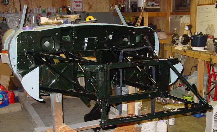
The completed assembly. A few things are lacking for the front suspension, most notably, the anti-roll bar and, of course, the brakes. At this point it does in fact look like a front end again!
Actually getting the cotter key in place is a real trick. The cotter key that came with my kit was actually slightly larger than the hole it was supposed to fit into. I was able to narrow the key by some deft work using my wire wheel on my grinder. It didn’t take much, obviously. (I cleaned the hole, too, with a drill bit.) You will need to bend the cotter key at two points, roughly in thirds along the key.Make the bends about 140°. You can also gently bend the whole cotter key into a curved shape about a quarter of a circle. These bends will make it possible for you to get the key into the hole on the stub axel end. Once you get the key into the hole, you shove it through and straighten the key while it’s in place. After the key is in place, you bend the halves of the key around the castellated nut, locking the nut into place.
First, a larger picture than I usually post. I beg forgiveness for the size of the shot, but I figured the compressed GIF image sacrificed too much accuracy in color. Fatter JPEG format will do.
The picture shows the color a bit more clearly than the previous shot did, but still the photograph doesn’t quite do opalescent dark green justice. It is indeed more fiery than the flat web browser allows. You can probably see the strategy I am taking in rebuilding and spraying color. I am holding off with exterior sections of the car until the internal sections are more or less complete. This has the upside of allowing me to get a little better with the spray gun before I attempt shooting color on the parts of the car that are most easily seen — and therefore more sensitive to my ineptitude with the sprayer. It has the downside of making any painting a big deal, since everything needs to be masked and cleaned and fussed over. Doing the entire job in one fell swoop would be more efficient, perhaps.
But if I were worried about efficiency, I wouldn’t be restoring this car, now, would I!
The primed front frames were sprayed with sealer and then color was applied. They were sprayed separately and then assembled onto the firewall (front bulkhead). I had replaced most of the bolts and nuts with grade 8 hardware, replated with zinc and then treated with zinc blackener. The effect is quite nice. I decided to give the blackened zinc a try in spite of the hours I had spent doing the nickel plating the front suspension parts. The additional protection was nice, but using correct color bolts convinced me.
As a small aside, I should add that I have been seeking opportunities for practice with the spray gun. Well, sometimes they have found me, too. The boys managed to wreck the 1995 Dodge Ram pickup so that the insurance company totalled it — it doesn’t take much to total an old vehicle, even a truck. I settled for enough to get another old pickup (a Ford F-150) and I decided to keep the Ram. We fixed it with some pulling and sanding and new parts, basically the driver’s side front end. Mechanically the old thing is still in great shape, and the frame wasn’t harmed by the accident. This turned out to be a great opportunity to practice painting. It was, unfortunately, as hard as I remembered. The old truck looks good from 20 feet, but you do see a couple of runs if you stand much closer.
Oh, well, so long as it doesn’t happen on the Jag….
Front suspension rebuild started
I thought about calling this section “Sproing!” because of the trouble I have had with the upper wishbone “circlips” (also known as “snap fasteners” or “internal retainers”). I got new upper and lower ball joints/ball pins for the wishbones, and the upper kits were supposed to have included internal retainers. And one kit did, but the other replaced the internal retainer with an external retainer, which of course wouldn’t work at all. I fetched the old part that I removed that had the internal retainer and I figured I was set.
Never underestimate the power of tools that aren’t quite suited to the purpose.
I managed to let both of the good circlips fly off into the netherworld. In the vain hope that cleaning might scare up one of them at least, I grabbed the broom and swept the garage. No clip appeared. The second one flew off after I had opened the garage door to let light come in so I could search for the first lost circlip. Of course, it flew off into the rose garden and grape arbor with a sleek and fast zing. I told Aaron he could grab his metal detector and search, but he wasn’t motivated.
McMaster-Carr came to the rescue, and I will be expecting a box of 25 circlips sometime early next week, I suppose. That should give me enough circlips for, well, another eleven cars. Anyone need a circlip cheap?
Besides this little annoyance, there are others. I’ll be compiling tips for installation of the front suspension parts to publish later, probably in the next entry. It turns out that order of rebuilding and installation matters a bit, but it’s not complicated.
My intention in the beginning was to have a professional plater complete the nickel plating of the front suspension pieces. And, indeed, I made good on the intention on my side. I drove the parts down to a plater in Fayetteville, North Carolina — all sixty-some pounds of them. I was hoping that I’d be able to get an estimate and shake hands on the deal when I was there. I wasn’t in any particular rush, especially since I has seen on the web that this particular plater “took his sweet time.”
I ended up leaving the parts in the Rubbermaid container, because the fellow in back was mixing chemicals and couldn’t break away to look at the parts. The time for the project was “six to eight weeks,” a little longer than I had hoped but I would still have the parts in the summer. The estimate would be available Monday, I was told. It was Friday, so no problem.
Monday, I called. No estimate, but surely Wednesday. Wednesday, no estimate. Friday,nada. I waited another week for the estimate. Finally, thirteen days after I had dropped the parts off, I drove down to fetch them. The estimate wasn’t available, and there was mumbling on the telephone about the sandblasted parts being “too rusty.”
I figured that I would take a shot at plating larger pieces. If I messed things up, I could always send them off someplace other than Fayetteville.
Believe it or not, I was able to use the Caswell nickel plating kit that I had used for the smaller pieces. It was mainly a matter of finding plastic containers that were big enough for the part and that still did not have too great a volume so that my supply of nickel plating solution wouldn’t cover the part.
The toughest part to manage was the “upright,” which is a long enough part but also has a depth because of the fittings for the top and bottom ball pins, going in one direction, and the hole for the stub axel, going in the other.
I thoroughly cleaned the parts using the degreaser and removed any remaining rust — there was a little left, I must admit. I used the strong muriatic acid bath (one part muriatic acid to two parts tap water) and electrical charge to remove the remaining rust. The negative charge goes on the place you want the rust to go (the sacrificed steel part) and the positive charge goes on the part you’re cleaning. The top photo shows the upright being cleaned.
Plating itself was a little trickier, since I had to do the agitation of the nickel plating solution by hand. Since space was cramped, a bubbler or other agitation device wouldn’t fit. I used a plastic spoon or sometimes just jostled the part itself. The key is not to let any bubble form on the surface, since the nickel will then pit. Also, especially in the case of the upright, you have to place the piece in an orientation that will not allow the collection of bubbles, since the nickel won’t adhere to the section where the bubbles collect.
In the close quarters of the smaller container, you also have to watch out for “gassing” which seems to occur when the piece being plated is too close to the nickel anodes.
As for electrical sources, I used three AC-DC converters and, for very large parts, an old Sears battery charger. I doubt any other plating than nickel would have worked, since nickel plating seems to be pretty forgiving in matters of electricity. Zinc plating has been far fussier, I’ve found.
In the end, the nickel plate really worked well on the front suspension parts, but at the cost of considerable tedium and fussing with containers and chemicals. Plating took weeks. After everything was plated, I sealed the parts with a two-part clear coat made for bare metals. The suspension should be in good shape for a long while.
Pictures below show the parts as they looked in April before I tried to have them plated. The picture below that one shows the newly nickel plated parts. They shined up nicely!
When my dad was here, we inspected the tappets that accept pressure from the cams. One of these appears to have been damaged either by dirt or by corrosion. The surface of the plate where the cam touches has been pitted. This will probably have to be replaced, since a roughened surface like that will certainly wear the cam and also be significantly weakened itself. The other tappets show almost no wear at all. My dad says that the cams bear the most pressure of any parts in an engine. They look to me to be models of precision and efficiency.
A previous owner of the car seemed very happy with gold paint on the cylinder head and sprayed the entire outside. From what I can tell, only the area between the value covers and behind the cover over the timing chain sprockets was painted gold, the rest either left aluminum or polished. I removed the gold paint from the timing chain sprocket area, and prepped the rest by removing as much as possible of the gold paint. No chemical strippers were used, since I didn’t want to have to worry about unfortunate reactions with aluminum.
The gold paint I used was the “Oldsmobile Gold” engine paint from POR-15. From what I could tell, there was no difference in color from the paint in place on the head when I took possession of the car, which is certainly not to say that it was an original color. While I was removing paint I did notice (with some momentary excitement) that a “pumpkin orange” color lurked beneath the grime, but I’m assuming now that this was discoloration due to age or heat or both. The reason for the excitement? There are rumors, denied by Jaguar, that at least some early 3.8 liter engines were fitted with cylinder heads sporting a pumpkin orange paint.
Nickel plating small parts
Since I want to install the front subframes fairly soon, I decided I would go ahead and get a nickel plating kit from Caswell Plating and do the front suspension mounting brackets. The brackets fit into the subframe and really need to be installed at the time when the subframe is fitted. The pieces have surface area below the 16-square-inch per ampere of current that nickel requires. I was able to cobble together DC power sources to make about an amp, so 16-18 square inches was about the limit. Plating nickel is indeed easier than plating zinc. The electrical charge doesn’t have to be quite as precise, I think, for nickel. And, perhaps, experience counts a bit in plating. I was very pleased with the results.
Although Caswell suggests plating nickel for 60 minutes to get a plate that is for automotive applications, I went ahead and increased plating times to between 80 and 90 minutes. As with zinc plating, surface preparation really counts. I had already sand-blasted the suspension pieces, but just to make sure that I cleaned up all rust and old plate, I submerged the pieces in a “pickle” containing one part muriatic acid (hydrochloric acid) to two parts tap water. Then I attached the negative lead from a AC-DC converter to a sacrificial piece of steel (in my case an old drill bit) and the positive lead to the piece I wanted to clean.
The process of completely cleaning takes several minutes and I imagine that really rusty pieces would take longer. I wouldn’t leave the piece in the acid with electrical charge unattended or you might dissolve the piece. I generally took the piece out, buffed the faces with a wire wheel, and returned the piece for a short bath in the acid mixture to remove whatever flash rust might have appeared during the buffing. Then it was a matter of following the Caswell instructions, and of course adding some time to their recommended plating session. I did notice that the acid bath sometimes made the surface of the pieces rough, and so the buffing smoothed things out.
Bushes installed (with the Ray Livingston method, modified)
In a recent discussion on the Jag-Lovers E-type forum about bush installation, Ray Livingston provided a sensible way of doing the job. (As a matter of fact, Ray seems to be full of sensible solutions to problems one encounters with Jags!) His solution involved a pipe with an inner dimension slightly larger than the outer dimension of the bush, a threaded rod, nuts, and washers. Basically the Ray Livingston Method was simple: you fit the bush to the open side of the mounting bracket, slide the threaded rod through the pipe, then the bracket, and finally through the hole in the bush. Put washers on both ends of the rod, followed by nuts, and then tighten the nuts to squeeze the bush (sprayed with silicone as a lubricant) into the bracket and finally slightly into the pipe on the other side of the bracket.
Simple, elegant, and cheap.
Of course, if you have a big honker bench vise, you won’t need to use the threading bits. But Ray surmised that pulling the bush through with more pressure on the centermost parts of the bush would probably make the process easier. I discovered that he was right. Also, the Ray Livingston Method could probably be used with mounting brackets still on the car — while hauling a car to a vise or vice versa would be a bit more difficult.
My approach to bush installation was the Ray Livingston Method, Modified. Instead of pipe, I used holes drilled into a stout piece of wood and instead of threaded rod, I scrounged up a nice long carriage bolt that I had previously used in a press.
The holes that I drilled were 1 1/2 inches (for the larger brackets) and 1 1/4 inches (for the smaller). Two of the smaller brackets — I can’t remember now if they’re the for the upper or lower fulcrum shaft — are attached to the frame with three bolts that go into a fitting attached to the frame, sometimes slightly spaced with shims. These three-bolt brackets won’t lie flat on the surface of the wood, so I made a slight indent with the drill bit so that the piece would lie flush to the wood at the point where the bush was inserted.
I found that the bushes went into the larger brackets quite easily. The smaller brackets were a bit more of a challenge, since the bracket tended to slip into the hole in the wood, setting the pulling force a bit awry. This was a rather minor challenge, though. Once things were set, the bush slipped right in. You do have to fiddle a bit to get the bush to go in so that about the same amount of rubber appears on each side of the steel bracket. This sometimes means pulling too far and having to remove the piece, turn it upside down and pulling the bush back a bit.
The shop manuals seem to suggest that a man with a firm hand can install bushes. That is not the case, even with the soap-water mixture that Jaguar then recommended to lubricate the bushes. You need a device. And use silicone instead of soap. Silicone doesn’t harm the bush (at least the ones I got), and it won’t promote rust on the bracket.
The bushes I got are apparently “Metalastic.” At least they’re labelled as such.
The garage had a very special visitor over this weekend. My dad, Wallace DeLong, came up to North Carolina after making the rounds through Florida to see relatives and participate in a travel exchange with people in Sarasota. I was a little worried about suggesting that we take on a project with the old car, since I didn’t want to impose my restoration work on an unwilling participant, but it actually turned out that Dad wanted to do exactly that.
As I mentioned before, Stefan Roundy provided a fine replacement for the bent bonnet subframe. That piece, along with the replacement left subframe from Bill McKenna, meant that the front frame could be put together with sound pieces. The bent up bonnet frame meant that the bonnet itself hung badly, and I was anxious to see whether the new bonnet subframe would straighten out the bonnet fit.
So, Dad and I installed the front subframes and mounted the bonnet on its hinges.
It fit squarely off the front bulkhead (firewall), though the bonnet measured just shy of an inch forward of the bulkhead — a bit too wide a space. We figured we needed to get the space to about a third of that.
We made some makeshift shims to insert into the hinges at the top. Basically, to bring the bonnet back, we had to make sure that the hinges were tightened until the hinge touched the area on the lower valance where they fit. No shims there — we needed to get the bonnet back as far as possible. Shims at that point would move the bonnet forward. Once we had done that, checked to see how the bonnet fit against the lower sections of the bulkhead and the upper sections. Things were slightly wider at the upper part than at the lower, meaning that we could raise the bonnet to even things out.
We did the raising in two ways: we raised the bonnet subframe by inserting a small shim between the subframe and the “picture frame” at the lower connections. And we placed shims over the top section of the bonnet hinge that pivots on the subframe. These two things did the trick. I do not think both will be necessary when we actually fit the bonnet after the suspension is in place, since the dynamics of the frame will change, and the bonnet subframe will probably sit slightly higher as a result. Roger Los mentioned that his bonnet fitting was simplified after installing the suspension pieces that fit into the picture frame. When I first read that, I felt it might be a little dubious, but seeing how the structure fits and acts when bolted down, it is very probable that the rigidity of those pieces will support the frame in the right places, with the result that shimming will be less of an issue. I think we’ll still need to shim upward, though.
The final gap between the rear of the bonnet and the front bulkhead ended up being about 3/8 inch — about a half centimeter, a little wider perhaps. I’m reluctant to go much narrower than this, simply because the thickness of the primer and paint will make things a little tighter. The gap is about right. It is amazing to see what a new bonnet subframe will do to the gap, at any rate. When we first mounted the bonnet back in August of last year, the gap was a crooked disaster.
Front suspension parts for plating
Although I didn’t subject my dad to the gritty glories of sandblasting, we did weigh and organize the front suspension pieces that are due for nickel plating. There is still one suspension fitting that needs disassembly and cleaning. It has resisted my efforts to extract some pretty rusty bolts. It’s soaking in penetrating fluid now. We have 64 pounds (about 30 kilograms) of metal to be plated. I’ve decided not to send off small parts like washers and nuts. These I will probably plate myself, as I’m leaning toward ordering a nickel plating kit from Caswell Plating. Bill McKenna says it’s actually less putzy than zinc plating, and that seemed simple enough.
The platers is located in Fayetteville, North Carolina, and UPS wanted almost $90 USD to ship the parts. I figure that the trip will be a pleasant drive, and I should know what the charge will be without having to spend $180 USD on shipping, roundtrip.
Cylinder head cleanup
The final thing we did was clean up the insides of the cylinders where the valves are located. Five of the six chambers had a good deal of grime in them, and the remaining one (number one) was not too bad — which made me suspicious. I think that the fuel mix was set rich, probably to avoid pinging? Wire brush attachments to the drill made quick work of the grime. The valves were obviously in good shape, and my dad and I wondered if the valves were recently replaced in an overhaul. Dad looked pretty closely at cylinder wear and the valves and felt that the last overhaul wasn’t that long ago, and the engine didn’t require a massive amount of work. We did not look closely at the crankshaft (most of which is still in place), and there is a high probability (in my mind at least) that the rebuild of the engine was focused on the top, and not the bottom. Even though the bearings for the piston rods weren’t bad, the keys in my mind are the crankshaft bearings. After all, it’s fairly easy to replace rod bearings, but to replace the crankshaft bearing you have to remove the crankshaft. Wear related to that is heavier on this engine, so I’m suspicious. When we get to the engine in earnest, the crankshaft comes off and the measuring begins.
Here’s what the chambers looked like after some cleaning:
Removing the guts of the right door was considerably easier than doing the left door, since I had already been through the process once. In a nutshell, this is the process: 1. Remove the window crank and the door latch handle by pushing the escutcheon away from the handle and pushing the lock pin through the hole. Remove the door panel 2. Remove the lower door hole access plates by drilling out the pop rivets that hold them in place. Scrape off the rubbery weather seal with a knife. 3. Remove the hardware attaching the chrome window rails from the top section of the door and from the two tabs inside the panel assembly at the bottom of the door. 4. Slide the window rails out through the top of the door carefully. 5. Remove the bolts and screws that affix the latch mechanism and the window crank mechanism to the door panel assembly. 6. Carefully pull the window glass through the top of the door and, after the glass is completely free, remove the window crank mechanism. You will have to adjust the crank mechanism to pull the glass free without binding the mechanism in the door panel assembly. 7. Remove the bolts that hold the exterior door latch handle. This is done inside the door panel. Then unclip the door latch mechanism from the inside of the latch handle. 8. Remove the handle from the outside of the door and then the latch assembly through the access holes in the door panel assembly. (You can remove the anti-drum material any time you can get a hold of it.)
By the way, the right door was in better shape than the left. There were no rust holes, and what rust there was stayed on the surface. It hung a little better than the left door, too. We did a little channel work on the left door, but the right door didn’t really need anything. I’ll probably get fussier, though, and mess with the fit a little bit.
Right front suspension partially disassembled
We removed the right front suspension intact a while ago, but it became time to disassemble it. I would like to have the wishbones, the fulcrum shafts, and other parts nickel plated, so we needed to completely take the thing apart. Also, many internal parts will need replacement, such as the brake cylinder rings and rubber parts and the wheel bearings. We were able to get much of the assembly apart, but I decided to bring the tough-to-disassemble parts into a local British automobile dealership and service shop. They had the tools and the experience with the items to take them apart completely, and I didn’t have to puzzle over it.
I have already the retrieved the disassembled parts from the shop (I’m writing this on 23 April), though I haven’t looked at the work yet. We have another suspension assembly to take off the front frame, and I’d like to get it into shape for plating. It’s still not clear to me how much nickel plating will actually cost. This is not super smooth chrome plating for a bumper but much rougher, and I’m hoping it won’t cost too horribly much.
It would be nice to have a “rotisserie” to mount the car body on. Such things are do-able, and I’ve seen them around, but I’ve not wanted to invest the time into building such a fancy rotating mount for the car. I suppose it would be nice, but we’ll flip this car over as need be. That said, I did need to create something to make it easier to move the body out of the way when we weren’t going to be working on it. I used lumber we had saved from an old chicken coop and four middle duty casters from the lumber yard to build a rolling rack. It stands about two feet high, and it carries the car quite high — perhaps a little too high. But it’ll do. And it was really nice to be able to roll the car body to the side to sweep the floor and clean up. It’ll practically be necessary once we need to move larger parts (like the bonnet) out of the garage to work on. The fact that it’s fairly high is also a nice feature, since I won’t have to be bending down all of the time to work on areas in the interior.
Aaron and I continued to disassemble the tubular steel frame, especially the right side suspension and frame pieces. We got everything apart, except for the lower wishbone and the torsion bar. these are still stubbornly affixed to the frame. The wishbone is free, but it is held to the frame by the torsion bar. I suspect that we’re either missing a piece to remove or the thing is just plain stuck. We ran into some difficulty removing a couple of the larger bolts, and we had to resort to heating up the nut after penetrating fluid failed to loosen things up. Heat worked like a charm. Thank goodness we have a pneumatic impact wrench!
Very Evil Rust (16 March 2003)
We did run into something I had dreaded, however.
I was thinking that the tubular steel frame was untouched by rust, but that proved not to be the case. When Aaron and I flipped over the frame assembly in order to get at some bolts more easily, we found two badly corroded areas on the left frame. One section near the picture frame (the central section the runs across the front, spanning the gap between the two side frames) was rusted through on the bottom. And a section below the battery area, on the underside of the tube, was rusted clear through. This damage wasn’t apparent from the top of the vehicle, though when everything was flipped over it was very easy to see.
I was hoping that I could avoid buying a new frame, since the things are pricey. But there is no way that I would attempt fixing this part. There is too much quite literally riding on it to test my skills. The tubular steel was also a very high tensile strength, and I simply do not have the tools to do the job. I think that the side frames cost around $ 750, and I should be needing to get one. The right side frame looks very good. I’ll know more about it after sandblasting it. I’m almost afraid to see what lies under the old paint.
Things have been getting too clean with the floors fitting and being sealed with POR-15. This weekend I turned to the front frame that we had removed long ago with the front suspension and steering mechanisms intact. The entire structure needs to be completely taken apart so that the steering, the suspension assemblies and the three-part frame itself can be thoroughly cleaned and, as the case may be, renewed.
I focused on the right suspension system. Actually much of the work consisted of spraying penetrating fluid on the nuts and bolts that needed to be removed or loosened. These nuts and bolts have been painted the body color, and as a matter of fact the shock absorber (the original Girling) and the upper wishbone itself were the body color of the car. That’s a very good indication that the car had been painted, since the original shocks were “Girling blue” and the upper wishbone was plated. I’m going to carefully remove the paint on both of these items to see what lies beneath the paint. To tell the truth, I have no idea what “Girling blue” really looks like. On all the photographs I’ve studied, I’ve never seen it. Depending on the shape of these shock absorbers, I might keep them and reinstall them. When I took ownership of the car, I did bounce it around a bit. The rear shocks were shot, but the front shocks seemed good still.
By the way, the English call shock absorbers “dampeners.” I was a little confused by the term when I was going through the shop manuals for guidance, and “dampeners” cause me to scratch my head a bit. But, of course, the name itself tells what the part does: dampen motion and “shock.”
I followed the shop manual instructions for removing the upper wishbone, since I have never done this kind of removal before. The instructions were quite good, but there was one problem with access to a bracket that holds the “fulcrum” of the wishbone onto the frame itself. The front bracket lies behind the shock absorber, and I found that I had to remove the upper shock absorber fastener in order to gain access to it. This fitting had three very stubborn bolts that took a great deal of penetrating fluid and many taps on the wrench to remove. I was careful not to be too free with my hammer, since replacing these pieces could be a real challenge. All the hardware is grade 8, however. And so, it is quite tough. The bolts themselves look untouched by the forty-some years they’ve sat. I’m guessing the a coating of paint may just have given them some extra life.
It would have been nice to remove the entire suspension assembly on the right, but some of the nuts and bolts are very much stuck. I figure I would treat them with penetrating fluid over the week and see if they will loosen up.
Smallish stuff
I am anxious to flip the car back to its normal state, since seeing the floors now has become tedious. I did some preparatory work to sealing the floors with POR-15, and this has required a bit of an adjustment in timeframe. I was hoping to get the entire floor coated with POR-15 this weekend, but the problem was fitting the rear floor stiffener. This piece covers an area of the floor that I definitely want to coat with POR-15, but that section becomes inaccessible once the stiffener is in place. As a result, I have to POR-15 the section before placing the stiffener. This takes planning — and time. Everything is now set, and I am planning on having the entire floor sealed by the end of the week.
The front end of the inner sill (the piece that is part of the front bulkhead) still needs to be fabricated. Today I found the template I used for the corresponding piece on the other side of the vehicle. With a simple flip, the template works for this side as well. I fitted the cardboard piece to the area to see what adjustments might need to be made. None needed. I can cut this piece and fit it sometime this week in the evening.
I’ve thought about calling one of these little chapters “The Car That Was Made Of Cardboard” — appropriate, since without cardboard from pop containers, the metalwork would have been much harder!
The front frame that holds the engine, the front suspension, and the bonnet was removed. Overall it was No Big Deal, though bolts on the left (driver’s) side were rusted tight and had to be drilled off. The heads of the bolts had fused, though the threads apparently are loose. I can move the cut-off bolts with my fingers now. I suspect that I won’t even need to worry too much about the assembly that attaches the frame to the “tub.” Although much of the hardware is in decent shape, I think I’ll be replacing all of the hardware when I reassemble the frame.
I took the frame off with the front suspension intact. I have to admit that I’m not thrilled with the prospect of dismantling the front suspension. But I did have to remove the frame in order to free up the body shell and make it easier to flip the entire body to fit the floor panels. The picture shows the front bulkhead half stripped. Over the course of the weekend, I managed to strip and sand most of the piece. I’m hoping that the weather holds so that I can prime the bulkhead and get some more POR-15 to lay over the primer as a sealant.
I had other things to do than work on the car, but the removal of the frame didn’t take very long.
Footwell Repair (10 November 2002)
I took on more rust repair. This time it was the left side footwell cover that makes up part of the front bulkhead. (This section appears on the right side of the bulkhead picture, since the picture is taken from the front toward the back. Thus, the directions get reversed. You always refer to the sides of the car as though you were in the car seat, looking forward.) The piece was bent on the bottom, and corrosion had significantly weakened the metal up a little less than an inch. The picture clearly shows the bend, and some rust is visible, though much of the rust is surface rust and not a concern.
The fix entailed cutting out the section of the footwell that was damaged, spot welding a panel behind the front side of the piece, and then attaching a new lower section of the footwell with spot welds and lap welds. This lower section has a tab that angles out from the front, and it is part of the way that the floors are attached. As we did with the left inner sill, we used 18-gauge steel to fashion the pieces. It’s not too tough to cut, but it is stiff and resists the bending. To make it easier to grab and bend, I made the tab about three-quarters of an inch big. Although the final product doesn’t need that big an angled tab, we can cut or grind off the excess after the floor panel is in place, too.
Perhaps I’m doing something wrong with spot welding, but I find that I often have a lot of grinding to do. And then sometimes I have little indentations or voids where the metal seems not to have stayed. I chalk it all up to the poor visibility. Put a welder’s mask on and see how much you can make out, even with blinding lights. But after the grinding and some touch-up welding the piece seemed pretty presentable. I used an angle grinder to do the smoothing, but of course there always are imperfections and ripples. A light coating of bondo smoothed out the surface.
It is perhaps a realization that creeps up on all car restorers: Bondo seems less and less despicable stuff. I suppose that’s healthy, so long as I don’t fall to the Dark Side, and start doing everything with bondo.
The footwell repair took the bulk of the day. Now I can see why this piece is bought and replaced rather than fixed. A replacement costs about $45 (US) or so, and I’ve seen them go on ebay for $25 (US). What’s my time worth? Well, at least this footwell is original, mostly.
It’s worth noting that the main rust damage on the front bulkhead was in the vicinity of the battery. As a matter of fact, I’ll have to build the battery compartment pretty much from scratch, since the HVAC Man did his trick with 26-gauge sheet metal and pop rivets on the area holding the battery. Also, we noticed that a diagonal slit was made along the left outside sill to insert more of the chintzy sheet metal — mainly on the front third of the outer sill. More pop rivets covered with bondo, too. What a treat! We were going to take off the left side outer sill, but we never got around to it. That can wait for another weekend. I do not believe the left sill will have as much corrosion uniformly along the bottom, though the front end of the sill has some damage.
 pieces a bit more permanently. This entailed setting the torsion bars (Oh, joy!) and putting the steering rack and tie rod assembly into place. I also fitted the shock absorbers. So, the only part that is not in place yet is the brake assembly. I figured that I would hold off on the front brakes until I can see the status of the rear brakes, which accept the Dunlop brake slave cylinders, as I understand it. (Classic Jaguar frequently fits the front brakes on the rear and then replaces the fronts with higher grade brakes.) That way, I should be able to get the rear suspension done and installed before I have to make a decision on the front brakes. If I fit the front brakes on the rear, I can also avoid doing a lot more nickle plating right away, though of course there are parts in the rear that will require plating. At this point I might just do the plating in one fell swoop in any case — it’s not an important decision at this point.
 the way, you need to attach the lower end of the shock absorber first, and then pull it up to fit the upper end.
 I thought about calling this section “Sproing!” because of the trouble I have had with the upper wishbone “circlips” (also known as “snap fasteners” or “internal retainers”). I got new upper and lower ball joints/ball pins for the wishbones, and the upper kits were supposed to have included internal retainers. And one kit did, but the other replaced the internal retainer with an external retainer, which of course wouldn’t work at all. I fetched the old part that I removed that had the internal retainer and I figured I was set.
 to a plater in Fayetteville, North Carolina — all sixty-some pounds of them. I was hoping that I’d be able to get an estimate and shake hands on the deal when I was there. I wasn’t in any particular rush, especially since I has seen on the web that this particular plater “took his sweet time.”
 When my dad was here, we inspected the tappets that accept pressure from the cams. One of these
  appears to have been damaged either by dirt or by corrosion. The surface of the plate where the cam touches has been pitted. This will probably have to be replaced, since a roughened surface like that will certainly wear the cam and also be significantly weakened itself. The other tappets show almost no wear at all. My dad says that the cams bear the most pressure of any parts in an engine. They look to me to be models of precision and efficiency.
 Caswell Plating and do the front suspension mounting brackets. The brackets fit into the subframe and really need to be installed at the time when the subframe is fitted. The pieces have surface area below the 16-square-inch per ampere of current that nickel requires. I was able to cobble together DC power sources to make about an amp, so 16-18 square inches was about the limit. Plating nickel is indeed easier than plating zinc. The electrical charge doesn’t have to be quite as precise, I think, for nickel. And, perhaps, experience counts a bit in plating. I was very pleased with the results.
 to the frame with three bolts that go into a fitting attached to the frame, sometimes slightly spaced with shims. These three-bolt brackets won’t lie flat on the surface of the wood, so I made a slight indent with the drill bit so that the piece would lie flush to the wood at the point where the bush was inserted.
 through Florida to see relatives and participate in a travel exchange with people in Sarasota. I was a little worried about suggesting that we take on a project with the old car, since I didn’t want to impose my restoration work on an unwilling participant, but it actually turned out that Dad wanted to do exactly that.
 bonnet fit against the lower sections of the bulkhead and the upper sections. Things were slightly wider at the upper part than at the lower, meaning that we could raise the bonnet to even things out.
 process: 1. Remove the window crank and the door latch handle by pushing the escutcheon away from the handle and pushing the lock pin through the hole. Remove the door panel 2. Remove the lower door hole access plates by drilling out the pop rivets that hold them in place. Scrape off the rubbery weather seal with a knife. 3. Remove the hardware attaching the chrome window rails from the top section of the door and from the two tabs inside the panel assembly at the bottom of the door. 4. Slide the window rails out through the top of the door carefully. 5. Remove the bolts and screws that affix the latch mechanism and the window crank mechanism to the door panel assembly. 6. Carefully pull the window glass through the top of the door and, after the glass is completely free, remove the window crank mechanism. You will have to adjust the crank mechanism to pull the glass free without binding the mechanism in the door panel assembly. 7. Remove the bolts that hold the exterior door latch handle. This is done inside the door panel. Then unclip the door latch mechanism from the inside of the latch handle. 8. Remove the handle from the outside of the door and then the latch assembly through the access holes in the door panel assembly. (You can remove the anti-drum material any time you can get a hold of it.)
 the wheel bearings. We were able to get much of the assembly apart, but I decided to bring the tough-to-disassemble parts into a local British automobile dealership and service shop. They had the tools and the experience with the items to take them apart completely, and I didn’t have to puzzle over it.
 building such a fancy rotating mount for the car. I suppose it would be nice, but we’ll flip this car over as need be. That said, I did need to create something to make it easier to move the body out of the way when we weren’t going to be working on it. I used lumber we had saved from an old chicken coop and four middle duty casters from the lumber yard to build a rolling rack. It stands about two feet high, and it carries the car quite high — perhaps a little too high. But it’ll do. And it was really nice to be able to roll the car body to the side to sweep the floor and clean up. It’ll practically be necessary once we need to move larger parts (like the bonnet) out of the garage to work on. The fact that it’s fairly high is also a nice feature, since I won’t have to be bending down all of the time to work on areas in the interior.
 spanning the gap between the two side frames) was rusted through on the bottom. And a section below the battery area, on the underside of the tube, was rusted clear through. This damage wasn’t apparent from the top of the vehicle, though when everything was flipped over it was very easy to see.
 the front suspension and steering mechanisms intact. The entire structure needs to be completely taken apart so that the steering, the suspension assemblies and the three-part frame itself can be thoroughly cleaned and, as the case may be, renewed.
 I had to remove the upper shock absorber fastener in order to gain access to it. This fitting had three very stubborn bolts that took a great deal of penetrating fluid and many taps on the wrench to remove. I was careful not to be too free with my hammer, since replacing these pieces could be a real challenge. All the hardware is grade 8, however. And so, it is quite tough. The bolts themselves look untouched by the forty-some years they’ve sat. I’m guessing the a coating of paint may just have given them some extra life.
 floor sealed by the end of the week.
 Thus, the directions get reversed. You always refer to the sides of the car as though you were in the car seat, looking forward.) The piece was bent on the bottom, and corrosion had significantly weakened the metal up a little less than an inch. The picture clearly shows the bend, and some rust is visible, though much of the rust is surface rust and not a concern.
 of the footwell with spot welds and lap welds. This lower section has a tab that angles out from the front, and it is part of the way that the floors are attached. As we did with the left inner sill, we used 18-gauge steel to fashion the pieces. It’s not too tough to cut, but it is stiff and resists the bending. To make it easier to grab and bend, I made the tab about three-quarters of an inch big. Although the final product doesn’t need that big an angled tab, we can cut or grind off the excess after the floor panel is in place, too.
 and start doing everything with bondo.