Bonnet mouth Bondo
We unbolted the top section and the lower section of bonnet in order to finish some last bits of welding of a tab and to bang forward the upper and lower “lips” of the mouth. These sections had been reinforced or completely replaced with fresh metal, and so the stuff was difficult to shape. The lower section of the bonnet was especially resistant to further pushing, though it went forward about a quarter of an inch in the center. The movement of the upper section was a little less, though this was less critical, since the upper section of the bonnet mouth needed less adjustment. Basically, when we flattened the portion of the center section above and behind the mouth, the effect was more or less achieved.
It was time to give up on further hammering and resort to, well, plastic resin.
I was not entirely happy that we got to this point. You always hope that the metalwork will get done and that the body filling part of the job will require about a teaspoon of Bondo, preferably less. It rarely actually ends up that way, and I doubt it ever ends up that way with a job the size of the one that we were doing on this old bonnet. The fact is that I was less and less assured that shaping the sheet metal of the bonnet would mean progress. We had come to the point when an adjustment here meant a whack to correct the adjustment itself. We were shaping ourselves into a mess, and the shape in any case was pretty much there.
Now, I have three rules for using body filler:
- Use it only when nothing else will do.
- Use it to smooth, not to shape.
- If you shape, consider buying a new part.
We had reached the point of rule number one. I feared (rightly) that rule number two was going to be transgressed. And so, rule number three kicked into effect. The part in question was the lower bonnet section, also known as the “bonnet valance.” Clearly, the metalwork that I had done was not in the right place. The lower “lip” section still was recessed and would require more than a smattering of body filler to bring it out to the point it needed to be. I estimated that we’d need to apply about a quarter inch of Bondo to about a five-inch stretch of the lower lip, roughly from the center toward the right side.
In effect, I would be using Bondo to shape, not just to smooth (and I wasn’t very happy about that). The prospect of getting the upper section of the bonnet smooth and flat was daunting enough. To tell the truth, I hate working on flat areas, since they betray the most delicate of waves and ripples. The E-type bonnet is largely a smooth flat area. To add to the difficulty, that flatness has a delicate curve, here and there, so you can’t just take a straightedge and drag it across the surface to determine “truth.” You have to find other ways of determining the curve and the flatness.
For Aaron and I at this point, the human hand is the best instrument we have to discover the ripples and unwanted curves.
The bonnet we were working on had at one time been turned into a single piece with welds along the intersections of the wings, the center section, and the lower section. Although the chrome “bead” was still intact along the top, the meeting of wing and center section below the headlights had been obscured by body filler. (I believe that some E-types were built without a bead there, though I think that feature was introduced well after 1963. It may have been something seen in the so-called “Series 1 1/2.”) When we disassembled the bonnet, we cut these hideous welds and removed the Bondo. It’s a bit unfortunate that we have to replace the lower chrome “bead” below the lights.
In order to make sure that the body filler would not seal the bonnet sections together, we inserted thin cardboard strips between them. This barrier keeps the body filler from spilling over the seam, and it will make it easier to disassemble the bonnet again. At present, there is about a centimeter of cardboard jutting out at the seams. Once we have smoothed the seams with Bondo on both sides of the seams, my plan is to literally grind down the cardboard with a sander, and then sand the Bondo across the seam. The cardboard should separate nicely, and the seam between the sections will be very consistent.
We still have a fair amount to do before we can do that final sanding, though. Small ripples in the center section of the bonnet are now smoothed, but we do have a few wide (and very slight) depressions between metal “humps.” We dealt with a few of these things already, and the trick was determining whether the exposed metal is in fact too high or if the Bondo lapping up against it is too low. It’s a trick. I think the best way of doing this smoothing is to move from the back portions toward the front, not from one side to another.
After we get the bonnet smoothed, we’ll run a straightedge along lines and see if we notice irregular sections. I think that will about do it until we can actually use tube lights against a glossy primer surface. Lights are always the giveaway.
One thing about this body filling: you really see the shape of the car forming before you — gratifying sight, indeed.
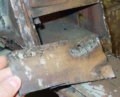 the outside of the “B”-pillar actually had some structural impact. Unfortunately, the way to obscure the fix was to apply bondo, and so the structural repair was apparent in a large lump of bondo about five centimeters from the base of the pillar, just under the door striker.
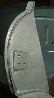 Then we measured the hole carefully, cut it out, and welded it into place. The tabs themselves were spot welded, and then along the perimeter we used a regular old butt weld.