Category Archives: Engine

May 2007 – New engine!

New engine! —New, at least for me

Very exciting! I picked up an engine to resolve the issues of the thrust washers and crankshaft. This one is a 4.2 liter XK from a 1979 model year XJ6. I used the free advertisement section of Jag Lovers to track it down. David Boger lives a little over two 
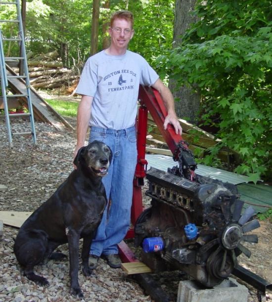
hours down interstate 85 from me, and so it was an easy pickup after we made the deal.

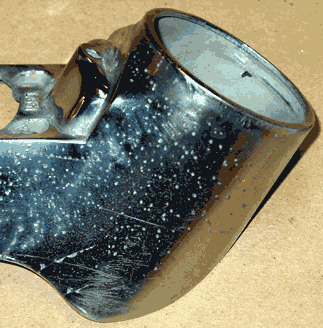
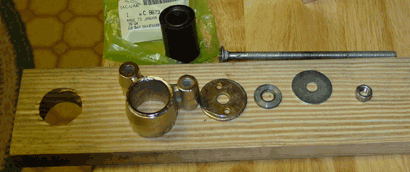
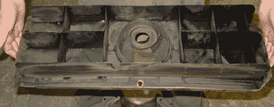
The engine is basically the same as the one that came out of my car, except that it was fuel injected (I didn’t need that) and a 4.2 liter. The water pump and belting is a little different, and (as the picture shows) the XJ6 has a fan attached via the water pump. It also has an electronic ignition, which I will keep. The block itself is configured a bit differently for the XJ6, since it uses the E-type engine mount points for the power steering pump (and something else on the other side). The XJ6 engine mounts are set a little further back. The nice thing is that you can still use the E-type mounts in their appropriate places — just remove te brackets for the other stuff and stick in the engine mount brackets. The cylinder head has a couple of extra holes for coolant, and some subtle changes that are less of a bother, probably. (See below for information about the head.) David provided the XJ6 exhaust manifolds that I’m going to try to use. The originals I have are fine, but I like the XJ manifolds, and I’d like to keep the heat shield in place, since damage to the bonnet paint over the manifolds has been reported.

David has about a dozen XJ6’s in his collection of parts cars, ranging from series one through three. He has a series one that looks like a good candidate for restoration — a right-hand drive model with some interesting details. It was damaged a little on an outer sill, but that was a pretty easy repair, I thought. He’s working on another XJ that’s perched on the ramp that you can barely see in the background of the picture. Instead of an XJ6, this one is an XJ12, with a front end full of metal. I don’t know what his ultimate plans are for the car, but it’s a good project. I think it would take me a long time to take on a V-12, though it would be fulfilling to complete … until you have to pay for the fuel, of course.

I walked his grounds, visited his horses, met his wife and 22-month old daughter. I determined he was a good man to buy an engine from. I certainly know where I’ll be able to find E-Type parts that might be interchangeable with the XJ series. And, seeing those old XJs made 
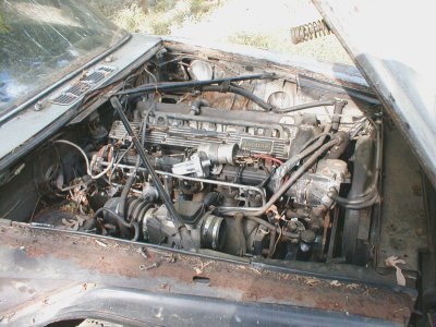
me wonder if I should try my hand at one of those eventually. I have an XJ8 (I think they call it an X308 model, or the like) now, and it’s a wonderful car. The earlier version XJ6 series has the same glove-like, natural quality. The interiors of David’s cars, though most of them were worn out, still had that Jaguar feel. In my opinion, the XJ6, series one through three, were nice cars, but the following boxy ugly version of the late 80s seems to have lost its way. Jaguar found the path again with the XJ model that currently is offered, I think.

He walked me to pay homage to the donor car, which sat at the end of a row, sans rear suspension, front end akimbo, left front panel gone, lights poked out — all probably mounted on other rides somewhere.

David is a square dealer, and he offered me the history he had of the engine and its donor car, telling me what did and did not work. He lives near Rockwell, North Carolina, which is not too far from Charlotte. He’s probably most available by email: david@everydayxj.com. I’m adding him to my list of suppliers, since there do seem to be useful overlaps of parts between the E-type and the good old XJs. [Added 20 January 2008: David has a website now: http://everydayxj.com.]

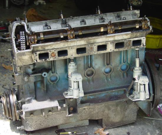
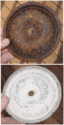
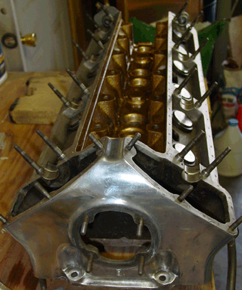
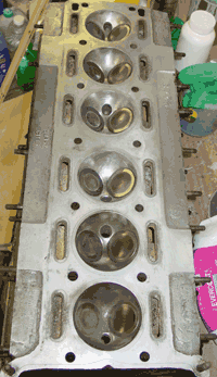
It’s been striking to see how much the early E-type engines were ornamented. The engine block from the XJ6, cast and fitted during the dread British Leyland years, was crudely sprayed a faded blue. The cylinder head on our old cars were painted gold and the area covering the timing chains was smoothed and polished, or at least brushed. The XJ6 head was barely extracted from the sand after it was cast and then quickly gone over with a grinder to remove casting seeps. and seams. No cosmetics in the late 70s, I’m afraid.

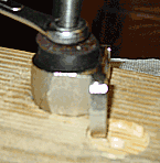
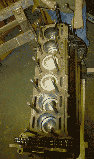
The “bottle jack” method of cylinder head removal

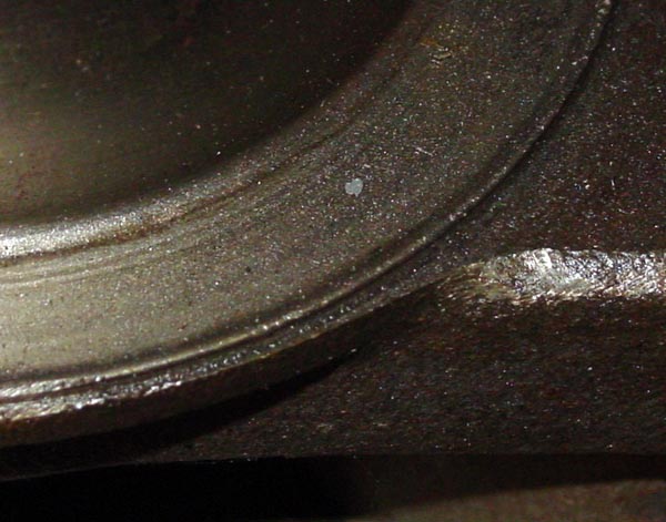
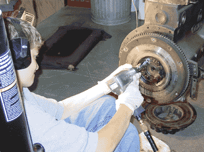
In short, the cylinder head was a bugger to get off. The head bolts had corroded, except for the pairs on each end. I guess this is quite common. I first thought that the head gasket was giving us the trouble, but quick taps of the bolts (with head nuts fittted, of course) quickly told us which ones were locked tight. They were the ones that didn’t budge or rattle in the least. Aaron squirted bolt loosener (PB “Blaster”), and that seemed to help a bit, and we made tiny headway to free the corroded bolts.

But a quick search on Jag Lovers brought up references to a “bottle jack” method that appeared to be quite effective. I have to admit that I was a little baffled, but at least I had a couple of hydraulic jacks. They have done various and good service on everything from cars to ninety-year-old floor spans. Why not on a cylinder head, too? When I was sitting at the computer, I had no idea where the things would go, but with jacks in hand and kneeling next to the engine, it was apparent.

The underside of the head juts some way out from the top of the block, and the block itself has a shelf-like flare near the bottom. The jack sits between these points. The picture tells the story, at least in part.

I think that if you have four hydraulic “bottle jacks,” you’d have the best luck. I had two, and Aaron and I were constantly shifting them to push the head off more-or-less straight. I was worried that with too much uneven pressure the head could be damaged or the bolts even more fixed in place. If you had six jacks, you’d probably be able to take off a stubborn head with very little trouble. I would do one thing differently, I think. I would probably situate a stout angle iron under the head before applying pressure. That would spread out the pressure and eliminate any marks from the top of the jack. However, you would have to make sure that the pressure from the jacks would be going slightly inward. Otherwise the angle iron could pop out — perhaps dangerously, given the pressure that can be exerted.

I had intended on detailing the differences between the 1963 and 1979 cylinder heads in this entry, but I think I’ll delay that a bit, since we hurried the head to the machinists. When it comes back all fit and shiny, it’ll be a better example to look at in any case. I hope that the next entries might help some other restorer do a similar transplant.

March 2007 – Bores and thrust washer damage

I’ve been picking away at the engine. The cylinder head has gotten a clean bill-of-health after inspection, pressure testing, and a shave. The SU carburetors are cleaned up, though not quite ready since replacement parts are needed. Bores are all measured, and they have little wear from the last rebuild, when .030-upsized pistons were installed. I have debated whether I should just go ahead and have new sleeves fitted and go back to the nominal bore of 3.4252″. Since the current bores are still in good shape, I think I’ll wait to do the more thorough rebuild. I’ll fit new rings on the old pistons.

But there are still issues that trouble this engine work. Back when Aaron and I took the engine apart, we discovered the thrust washers unseated, with one of them sloshing around the oil pan. Their absence took its toll on the crankshaft and a part of the engine block. Pictures below tell the story. The crankshaft might be repairable, assuming that a good submerged weld could build up the face where the thrust washer fits. A ring-like ridge stands up about 0.045″ from the face where the thrust washer fits. I believe that entire depression would need building up. The ridge itself bit into the engine block in the absence of the thrust washer, and the are where the crankshaft met the block has been beveled slightly. That area would also need squaring up.

Obviously, the question in my mind now is whether the crankshaft is salvagable — or, for that matter, the block.

Face on block. It’s a little oily and dusty but at least not rusty. The side of the bearing seat shows a semicircular groove cut into the metal. This groove is about at the outer edge of where the thrust washer fits. You can see that the impact of the crankshaft created a ridge of crushed metal on the face that accepts the crankshaft bearing.
Bevel on block. At the center of the picture it is apparent that the friction from the crank absent a thrust washer has ground the face into a slight bevel. This should be square, especially since the area serves to hold the thrust washer. This damage might not be that recent, actually, since it might be the reason why the thrust washer fell out. A relatively recent rebuild might have fit a new thrust washer in the damage section without repairing the damaged faces. The thrust washer we took out were beaten up by being loose, but they did not look particularly worn. The groove is easily seen, of course.
The thrust washer face on the crankshaft. The ring-shaped rise is apparent in the photograph. The difference between the top of the ridge and the bottom of the depression is abut 0.045″. I actually think that the rise is about the correct height on the thrust washer face, though I can’t be sure. It’s still a mystery to me how the thrust washers are kept in position, unless they are capped in some fashion when the crankshaft is secured.

November/December 2004 – Various and sundry

Interior insulation and sound dampener

From the outset of the restoration, I’ve been planning on insulating the interior and inside the trunk, especially below the spare tire storage and fuel tank area. I’ve kept an eye on products that would do the job well. I found two good candidates — Dynamat which is available through Classic Jaguar in Austin, Texas, and Fatmat which looks to be a less expensive Dynamat knock-off. The products are very similar: basically a laminate product with a flexible rubber-like substance laid over an aluminum or perhaps mylar substrate. Thicknesses vary, and the products include their own adhesive backing.

I felt that the Dynamat and Fatmat products were overpriced, since the technology doesn’t look that revolutionary. However, the Dynamat products look like they are textured to optimize sound deadening, as perhaps are the Fatmat counterparts. They do have the advantage of being sized and packaged for automotive use. Since I’m not planning on putting a huge subwoofer in my car (as a matter of fact it won’t even have a radio!), I won’t need optimal sound deadening. I’ve looked around for similar products, and I ended up with a good match in an HVAC duct wrap. It’s made the same as Dynamat/Fatmat and ends up being about a quarter of the price. Physical properties are similar, though the sound deadening properties of the duct wrap has to do with absorbing vibration on the foam side. The aluminum sheet is not perforated or otherwise adapted for sound deadening.

I used two differenty types of mat, actually. The predominant type was the aluminum covered foam, but I did use a purple foam mat as well in the front of the footwell. It is actually a foam pad used for softening the floor for exercise, but it is tough and will absorb vibration and sound well. Since it is durable, I’m thinking about using it as a backing for the “hardura” covers of the door sills and the floor of the trunk. The only concern I have (and it is not inconsiderable) is that the purple mat also has a “nubbly” texture that could (most certainly would?) show through the surface of vinyl. That said, this purple stuff is more durable than the aluminum foam. It would perform well in areas where there would be little other padding (felt or otherwise) and where constant crushing might be expected.

On the installation: I wanted to make sure that the foam would stay in place. Even though the aluminum foam was designed with an adhesive backing, I decided to cover the panels with contact cement so that the foam would stick with more vigor. The purple foam, of course, required full contact cement treatment, since it had no adhesive backing at all. I also used aluminum tape to cover all the joints, and those joints were prepped with contact cement as well. Things stuck very well, and there shouldn’t be any loose edges anywhere for a long time. When I fitted the mat, I cut away to leave bolts or holes exposed so that I can get to them later more easily. I also cut away foam from nuts that would otherwise have become lumps in the surface. The mat will even those out a bit.

Redoing air filter canister assembly

The air filter assembly consists of a large cannister and a triangular-shaped top that directs clean air from the cannister to the intake manifolds. A replacable air filter sits inside the cannister. The canister was especially rotted with rust in the base, and the round retaining plate that holds the filter in place was also badly rusted. I really don’t know why this would have been so badly rusted, since I would have thought that it was fairly protected from moisture. The inside of the canister may not have been painted — at least that’s what I’d suspect from the condition of the parts.

The canister was especially bad at the base, where there is a “false floor” with four round holes showing the real floor of the cannister about an inch under the false floor. I suspect this doubling was an attempt to baffle the air flow and even out the circulation of incoming air. The space between the floors would also serve to capture grits and larger objects so that they wouldn’t blow around near the filter.

I did the POR-15 treatment on these badly rusted items, and I rebuilt a small section around one of the canister floor holes that was enlarged by depleted metal. In order to get the coating to cover inside the section between the doubled floors, I poured some POR-15 into the cavity and shook it around until I was convinced that the inside surfaces were covered. I used basically the same prep as I did with the fuel tank, except that I had a much more accessible area to treat. The round retaining plate was treated in the same manner, and there I had to repair a hole or two with mesh and POR-15. It wasn’t pretty even after the treatment, since the surface was so badly pitted, so I used a bit of filler to smooth the surface a bit. This was cosmetic and probably a waste of time, since the piece is completely obscured and only sees the light of day when you change the air filter. I painted both that round piece and the inside of the canister a metallic, so it looks a little too silvery to be real metal, but at least it’s got another protective coat of paint on it.

The cannister is supposed to be black, at least for the 1963 model year. There has been some disagreement about this, since some cannisters apparently are hammered silver/grey in their current incarnation. The pictures I consider to be authoritative all show a black cannister with a hammered silver/grey triangular air filter manifold. So, I sprayed the outside of the canister and its clamp-on top gloss black.

They look pretty good — better, in fact, than I was thinking would be possible when I first looked at the rusted cannister bottom.

The air filter “plenum” is a triangular shape. Early 3.8 E-types also had a smooth top of the plenum, but they also had flanges that extended outward at the seam of the two shells making up the part. My plenum is smooth, too, though it doesn’t have flanges. Also the inside of the top shell has three grooves that roughly correspond to the grooves that later appeared on the tops of plenums beginning sometime late in the 1964 model.

I didn’t use a stripper on this piece, because paint strippers will also attack the fibreglass resin. To prep the surface, I sanded the old finish and removed any paint that was flaking or loosened with age. The metal pieces for mounting the manifold to the intake are attached with pop rivets, four on top and four on bottom. I removed the top rivets before repainting, but I left the bottom ones on. They are for all practical purposes invisible, and I wanted to lessen the risk of damaging the painted surface when I riveted. The top pop rivets were replaced with new.

Parts for repair and replating

Once you get paint on a car, having to wait for the trim becomes increasingly unbearable. I lessened the strain by quickly putting on the chrome surround that marks the edge of the license plate recess on the back of the car. And, of course, I dragged out whatever chrome I could find to see if there was some piece that was acceptable at least to hold against the body just to see chrome gleam against body color. Alas, my chrome isn’t in very good shape, and so I have to ship it off to have it repaired and rechromed.

I suppose that the taillights are the worst of the chrome pieces. They had suffered the elements most directly. The exterior door handles were probably the next worst. So, those were the parts that were packed up and sent away to a small chrome business in California. The fellow has some experience with 1963 Jaguar parts, and a fellow Jag restorer in the area said he would inspect the repaired parts before they would be sent off to the chroming shop. I’ll provide more information (and, I hope, a nice plug for the refinishing shop) when I get the parts back. I gave up finding a plater in North Carolina. While there are commercial platers around, they want sizeable and regular orders. The single “one-off” plater I found in Fayetteville, North Carolina, turned out not to be very responsible and so I rescued my suspension parts and did them myself. I don’t want to mess with chroming, however. It’s more of a challenge than I want to take on, especially when it comes to replating pot metal.

If things go well with the taillights and door handles, I’ll be sending the same California shop my bumpers for the treatment. They’re not as pitted as the pot metal, of course, but they need some attention.

The front sidelights turn out to be in acceptable shape. Whatever imperfections are on the chrome are small and they are tightly nestled against the bonnet in any case. I will need to work those a bit to get them to fit on the bonnet correctly, though. I’m not going to do any grindiing until the bonnet is sitting pretty on the body, since the shape of the bonnet seems to be fairly fluid until it’s actually in place. The interior chrome, for the most part, is also in good shape. The inside door handles are right at the tipping point for new chrome, and the chrome post that holds the rear view mirror is a wreck. I think it’s due a replacement, not a repair. The various escutcheons and ornaments on the dash and in the interior look good. With a cloth buffing, they’ll be nice.

IRS is next

While I had the entire male crew around, we lifted the IRS onto a work table. It’s going to get the attentions of mid-winter garage work.

April 2004 – Cylinder head paint, small plating, bushes installed

Cylinder head gold paint

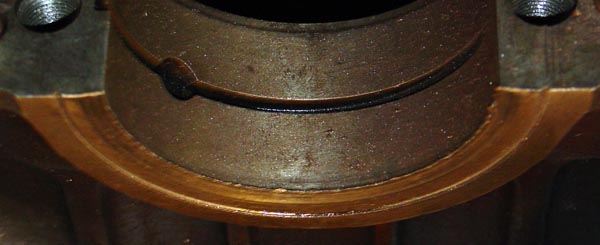
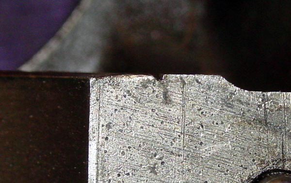
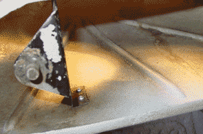
When my dad was here, we inspected the tappets that accept pressure from the cams. One of these 
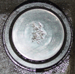
appears to have been damaged either by dirt or by corrosion. The surface of the plate where the cam touches has been pitted. This will probably have to be replaced, since a roughened surface like that will certainly wear the cam and also be significantly weakened itself. The other tappets show almost no wear at all. My dad says that the cams bear the most pressure of any parts in an engine. They look to me to be models of precision and efficiency.

A previous owner of the car seemed very happy with gold paint on the cylinder head and sprayed the entire outside. From what I can tell, only the area between the value covers and behind the cover over the timing chain sprockets was painted gold, the rest either left aluminum or polished. I removed the gold paint from the timing chain sprocket area, and prepped the rest by removing as much as possible of the gold paint. No chemical strippers were used, since I didn’t want to have to worry about unfortunate reactions with aluminum.

The gold paint I used was the “Oldsmobile Gold” engine paint from POR-15. From what I could tell, there was no difference in color from the paint in place on the head when I took possession of the car, which is certainly not to say that it was an original color. While I was removing paint I did notice (with some momentary excitement) that a “pumpkin orange” color lurked beneath the grime, but I’m assuming now that this was discoloration due to age or heat or both. The reason for the excitement? There are rumors, denied by Jaguar, that at least some early 3.8 liter engines were fitted with cylinder heads sporting a pumpkin orange paint.

Nickel plating small parts

Since I want to install the front subframes fairly soon, I decided I would go ahead and get a nickel plating kit from 
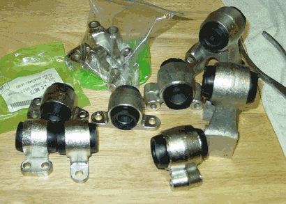
Caswell Plating and do the front suspension mounting brackets. The brackets fit into the subframe and really need to be installed at the time when the subframe is fitted. The pieces have surface area below the 16-square-inch per ampere of current that nickel requires. I was able to cobble together DC power sources to make about an amp, so 16-18 square inches was about the limit. Plating nickel is indeed easier than plating zinc. The electrical charge doesn’t have to be quite as precise, I think, for nickel. And, perhaps, experience counts a bit in plating. I was very pleased with the results.

Although Caswell suggests plating nickel for 60 minutes to get a plate that is for automotive applications, I went ahead and increased plating times to between 80 and 90 minutes. As with zinc plating, surface preparation really counts. I had already sand-blasted the suspension pieces, but just to make sure that I cleaned up all rust and old plate, I submerged the pieces in a “pickle” containing one part muriatic acid (hydrochloric acid) to two parts tap water. Then I attached the negative lead from a AC-DC converter to a sacrificial piece of steel (in my case an old drill bit) and the positive lead to the piece I wanted to clean.

The process of completely cleaning takes several minutes and I imagine that really rusty pieces would take longer. I wouldn’t leave the piece in the acid with electrical charge unattended or you might dissolve the piece. I generally took the piece out, buffed the faces with a wire wheel, and returned the piece for a short bath in the acid mixture to remove whatever flash rust might have appeared during the buffing. Then it was a matter of following the Caswell instructions, and of course adding some time to their recommended plating session. I did notice that the acid bath sometimes made the surface of the pieces rough, and so the buffing smoothed things out.

Bushes installed (with the Ray Livingston method, modified)

In a recent discussion on the Jag-Lovers E-type forum about bush installation, Ray Livingston provided a sensible way of doing the job. (As a matter of fact, Ray seems to be full of sensible solutions to problems one encounters with Jags!) His solution involved a pipe with an inner dimension slightly larger than the outer dimension of the bush, a threaded rod, nuts, and washers. Basically the Ray Livingston Method was simple: you fit the bush to the open side of the mounting bracket, slide the threaded rod through the pipe, then the bracket, and finally through the hole in the bush. Put washers on both ends of the rod, followed by nuts, and then tighten the nuts to squeeze the bush (sprayed with silicone as a lubricant) into the bracket and finally slightly into the pipe on the other side of the bracket.

Simple, elegant, and cheap.

Of course, if you have a big honker bench vise, you won’t need to use the threading bits. But Ray surmised that pulling the bush through with more pressure on the centermost parts of the bush would probably make the process easier. I discovered that he was right. Also, the Ray Livingston Method could probably be used with mounting brackets still on the car — while hauling a car to a vise or vice versa would be a bit more difficult.

My approach to bush installation was the Ray Livingston Method, Modified. Instead of pipe, I used holes drilled into a stout piece of wood and instead of threaded rod, I scrounged up a nice long carriage bolt that I had previously used in a press.

The holes that I drilled were 1 1/2 inches (for the larger brackets) and 1 1/4 inches (for the smaller). Two of the smaller brackets — I can’t remember now if they’re the for the upper or lower fulcrum shaft — are attached to the frame with three bolts that go into a fitting attached to the frame, sometimes slightly spaced with shims. These three-bolt brackets won’t lie flat on the surface of the wood, so I made a slight indent with the drill bit so that the piece would lie flush to the wood at the point where the bush was inserted.

I found that the bushes went into the larger brackets quite easily. The smaller brackets were a bit more of a challenge, since the bracket tended to slip into the hole in the wood, setting the pulling force a bit awry. This was a rather minor challenge, though. Once things were set, the bush slipped right in. You do have to fiddle a bit to get the bush to go in so that about the same amount of rubber appears on each side of the steel bracket. This sometimes means pulling too far and having to remove the piece, turn it upside down and pulling the bush back a bit.

The shop manuals seem to suggest that a man with a firm hand can install bushes. That is not the case, even with the soap-water mixture that Jaguar then recommended to lubricate the bushes. You need a device. And use silicone instead of soap. Silicone doesn’t harm the bush (at least the ones I got), and it won’t promote rust on the bracket.

The bushes I got are apparently “Metalastic.” At least they’re labelled as such.

March 2004 – Bonnet test fit, plating prep, cylinder head cleanup

Bonnet test fit

The garage had a very special visitor over this weekend. My dad, Wallace DeLong, came up to North Carolina after making the rounds 
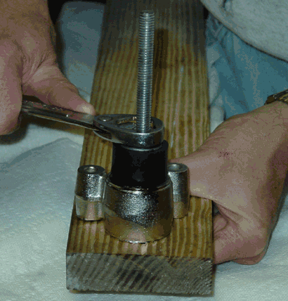
through Florida to see relatives and participate in a travel exchange with people in Sarasota. I was a little worried about suggesting that we take on a project with the old car, since I didn’t want to impose my restoration work on an unwilling participant, but it actually turned out that Dad wanted to do exactly that.

As I mentioned before, Stefan Roundy provided a fine replacement for the bent bonnet subframe. That piece, along with the replacement left subframe from Bill McKenna, meant that the front frame could be put together with sound pieces. The bent up bonnet frame meant that the bonnet itself hung badly, and I was anxious to see whether the new bonnet subframe would straighten out the bonnet fit.

So, Dad and I installed the front subframes and mounted the bonnet on its hinges.

It fit squarely off the front bulkhead (firewall), though the bonnet measured just shy of an inch forward of the bulkhead — a bit too wide a space. We figured we needed to get the space to about a third of that.

We made some makeshift shims to insert into the hinges at the top. Basically, to bring the bonnet back, we had to make sure that the hinges were tightened until the hinge touched the area on the lower valance where they fit. No shims there — we needed to get the bonnet back as far as possible. Shims at that point would move the bonnet forward. Once we had done that, checked to see how the 
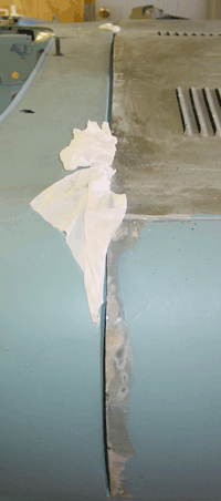
bonnet fit against the lower sections of the bulkhead and the upper sections. Things were slightly wider at the upper part than at the lower, meaning that we could raise the bonnet to even things out.

We did the raising in two ways: we raised the bonnet subframe by inserting a small shim between the subframe and the “picture frame” at the lower connections. And we placed shims over the top section of the bonnet hinge that pivots on the subframe. These two things did the trick. I do not think both will be necessary when we actually fit the bonnet after the suspension is in place, since the dynamics of the frame will change, and the bonnet subframe will probably sit slightly higher as a result. Roger Los mentioned that his bonnet fitting was simplified after installing the suspension pieces that fit into the picture frame. When I first read that, I felt it might be a little dubious, but seeing how the structure fits and acts when bolted down, it is very probable that the rigidity of those pieces will support the frame in the right places, with the result that shimming will be less of an issue. I think we’ll still need to shim upward, though.

The final gap between the rear of the bonnet and the front bulkhead ended up being about 3/8 inch — about a half centimeter, a little wider perhaps. I’m reluctant to go much narrower than this, simply because the thickness of the primer and paint will make things a little tighter. The gap is about right. It is amazing to see what a new bonnet subframe will do to the gap, at any rate. When we first mounted the bonnet back in August of last year, the gap was a crooked disaster.

Front suspension parts for plating

Although I didn’t subject my dad to the gritty glories of sandblasting, we did weigh and organize the front suspension pieces that are due for nickel plating. There is still one suspension fitting that needs disassembly and cleaning. It has resisted my efforts to extract some pretty rusty bolts. It’s soaking in penetrating fluid now. We have 64 pounds (about 30 kilograms) of metal to be plated. I’ve decided not to send off small parts like washers and nuts. These I will probably plate myself, as I’m leaning toward ordering a nickel plating kit from Caswell Plating. Bill McKenna says it’s actually less putzy than zinc plating, and that seemed simple enough.

The platers is located in Fayetteville, North Carolina, and UPS wanted almost $90 USD to ship the parts. I figure that the trip will be a pleasant drive, and I should know what the charge will be without having to spend $180 USD on shipping, roundtrip.

Cylinder head cleanup

The final thing we did was clean up the insides of the cylinders where the valves are located. Five of the six chambers had a good deal of grime in them, and the remaining one (number one) was not too bad — which made me suspicious. I think that the fuel mix was set rich, probably to avoid pinging? Wire brush attachments to the drill made quick work of the grime. The valves were obviously in good shape, and my dad and I wondered if the valves were recently replaced in an overhaul. Dad looked pretty closely at cylinder wear and the valves and felt that the last overhaul wasn’t that long ago, and the engine didn’t require a massive amount of work. We did not look closely at the crankshaft (most of which is still in place), and there is a high probability (in my mind at least) that the rebuild of the engine was focused on the top, and not the bottom. Even though the bearings for the piston rods weren’t bad, the keys in my mind are the crankshaft bearings. After all, it’s fairly easy to replace rod bearings, but to replace the crankshaft bearing you have to remove the crankshaft. Wear related to that is heavier on this engine, so I’m suspicious. When we get to the engine in earnest, the crankshaft comes off and the measuring begins.

Here’s what the chambers looked like after some cleaning:

September 2003 – Pistons removed, rear body shell block-sanded

This weekend marks the first year

It’s been a full year this weekend since Derek, Aaron, and I drove out to tidewater Virginia to pick up the old car. At that time I was thinking that I’d be driving the car a year after picking it up. But experience has taught me otherwise. I think we have made good progress nonetheless. It was my expectation that was out-of-line.

We’re watching Hurricane Isabel with some dread this weekend. It could end up being another Fran, some say, or worse. I just hope that the storm turns out to sea. There isn’t much to do about it except stockpile some water and make sure the flashlight works.

Pistons removed

I was thinking about a gradualist approach to remove the pistons, but I am thinking better of it now. We decided to remove the whole lot
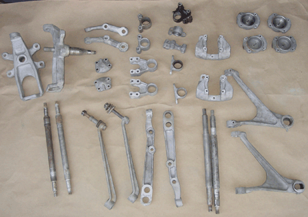
of them all together, so that we can take a closer look at the crankshaft. I spoke with my dad on the telephone over the weekend about the crankshaft. He tried replenishing bearings on an old engine once before, and they gave way shortly afterward. If the crankshaft is not true — if it has miniscule flatnesses especially — the crankshaft eats up the new bearings in short order. So, I’m going to look around for a machine shop that can check the crankshaft in all of its places and, if need be, turn and otherwise repair it.

As my dad said, now is the time to do it, when the engine is out and already apart. If the bearings fail and the crankshaft is the problem, doing the work later will be even more frustrating.

The piston rings look quite good. The two at the top are supposed to have a taper that narrows at the bottom, and these seem to have that shape still. I would have expected worn rings to be virtually square from wear. The lowest ring is actually composed of three parts: two solid and very thin rings surrounding a chain-like spacer. This assembly is the so-called “oil ring” — probably because it keeps most of oil in the crankcase and not spilling into the firing chamber above the pistons.

I haven’t looked everything up yet, but I’m thinking that the bearings that we took off the piston rods were the 0.010 inch oversize versions. Not only do the markings suggest that, but that kind of wear would fit with the 0.030 inch oversize of the pistons. From what I can tell that size bearing is the maximum as well.

Rear body shell block-sanded

I began block-sanding the body shell. It is a little tedious, but I am amazed at how something as simple as block-sanding can tease out slight imperfections in the body shape. I’ve been marking them with masking tape as I go along. Many are slight dips or flatnesses in inappropriate places, usually at a spot where we had to do a little repair or where panels meet. One area that appeared with the sanding was in a place I wasn’t expecting, just above the left rear wheel well on the rear quarter panel. I suspect that the car was bumped at some time or another and very lightly dented. We probably removed a smattering of Bondo when we stripped the paint and didn’t see (or feel) the flatness.

I was hoping to fire up the air compressor and let Aaron have a go at applying some primer, but I think now that block sanding the remainder of the body shell and making some final repairs would be a better idea. Then we can take on the entire body shell in one day, or at least the top portion. We are going to use some POR-15 “Tie-Coat Primer” which is formulated to bond to cured POR-15. We might not have needed it, actually, since the block-sanding is making the surface rough enough for regular primer to bond to. I already have the Tie-Coat Primer, at any rate.

I’ll post pictures of the marked up car later on. Block-sanding is really important, but it’s easy to overlook because spraying primer is a heck of a lot more fun!

August/September 2003 – Engine stand, oil pan removed

Engine mounted on stand

We went to a local auto parts shop and bought an engine stand. I had looked around and I thought they were much more expensive 
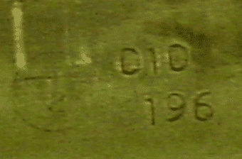
and was delighted that we could walk away with ours for under $40 USD. We hadn’t really explored the engine — like the removal of the oil pan to inspect the crankcase area — and the engine stand made this much more possible. Most engine stands connect to the engine by the bolts used to attach the bell housing at the rear end of the engine block. (I’m not sure exactly how new-fangled sideways engines are attached to their engine mounts. I assume that there is a wholly different breed of engine stands for such engines.)

In order to fit the engine onto the engine stand, we had to remove the clutch assembly and the flywheel. These two parts are supposed to be marked when they are balanced, but we were unable to find the balance marks. The clutch and the drive plate were in pretty good shape. The clutch had a little wear, but it was still in servicable condition when the car was put into storage. Of course, we’ll fit a new clutch. The drive plate is smooth and not pitted at by rust. It just needs a good cleaning. To remove the flywheel we were thankful to have had a pneumatic impact wrench. The ten bolts were pretty tight, though not fused with rust. They are very closely seated, so getting the socket around the bolts was a bit challenging. Everything came off nicely after a little tapping.

Oil pan removed, thrust washers found loose

When we took off the oil pan, we searched for any extra parts that might have worn off. We found the thrust washers loose in the crankcase area. They probably fell out some time ago. 
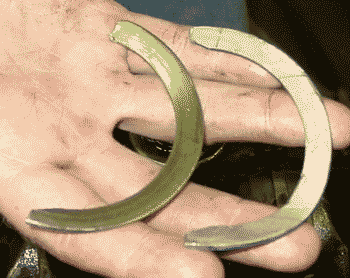
At this point we have not investigated the damage that may (or, we hope, may have not) been caused by the lack of thrust washers. They were a bit of a mystery at first, since they obviously were not crankshaft bearings and they gave the impression of being halves of a single large washer that was split. The thrust washers fit on both sides of the middle crankshaft support. I think they stabilize the crankshaft from forward and backward movement, though I don’t know how critical they are, since it would seem to me that most of the strain on the crankshaft would be vertical and horizontal — coming from the up and down motion of the pistons. A cursory look at the middle support and the surrounding fittings revealed no apparent damage. We’ll need to see about the wear in this area, just to see if the section is so large that the thrust washers won’t fit snugly.

One of the thrust washers was a bit bent on one end, and there was some shearing at one end. It probably slipped out and was bent and pinched on its way out. After the first one came out, the other one was probably much looser and more or less fell out intact. These pieces are supposed to be marked if they are oversized, and I didn’t see any markings to that effect. (I didn’t look closely, I have to admit.) These pieces may not have been correctly reinstalled.

Oil pan and pan baffles cleaned and reassembled

The amount of sludge on the bottom of the oil pan was less than what I’ve seen on other engines, making me think that the last overhaul of this engine wasn’t that long ago. We scrubbed the aluminum oil pan after removing the baffles. A bit of wiping, rinsing with kerosene, and some scrubbing with liquid laundry detergent got it nice a shiny. The baffle was a little more permeated with oil and dirt and so it didn’t come out quite as clean. We removed all the sludge, though, and reassembled the pieces. It is a nice clean job now.

The pictures show the top and bottom views of the oil baffle. The purpose of the individual box-like compartments isn’t really clear to me. The oil pump sump fits at the center of the piece, in the round screen bowl.

Piston heads cleaned, markings revealed

We used steel wool, kerosene and elbow grease to remove carbon deposits that were mainly on the exhaust port side of the piston heads. 
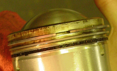
I suppose this wasn’t really necessary at this point, but it can do nothing but good to remove some of the collected grit from the cylinders and pistons. This cleaning had the benefit of allowing us to see markings on the pistons that show that these pistons are oversized by 0.030 of an inch. That is the largest size that Jaguar recommends before resleeving the cylinders and resizing the pistons to their initial measurements. The markings also confirm absolutely that the engine has been overhauled (not an unusual thing, of course — it would be far more unusual to find an engine of this vintage that had not been overhauled).

The pistons themselves look pretty good. They are good solid circles, no blowouts or weird tapers. I figure that we’ll pull each one out, one at 
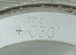
a time, to replace the rings and bearings. Then after one is back in place, we’ll remove the next one, and so on. This, of course depends on whether we’ll need to remove the crankshaft to do whatever needs to be done about the thrust washers. At this point, however, I’m thinking that the issue with the thrust washers was a matter of incorrect installation or perhaps a misfit of part. As a matter of fact, it’s not clear to me that the thrust washers were in fact replaced at the last overhaul. The ones that were mangled may indeed have been the originals. I don’t know yet.

We’ll need to get a tool to remove the rings, I suppose. I can’t recall what my dad and I used to remove rings, unless we simply used plyers and didn’t worry about damaging them. I do recall using cut Campbell Soup cans to compress the rings around the pistons to reinstall them. That was long ago, though, and on a Mustang that was about two years younger than this old Jag.

Good memories — and ones that I hope might be passed to the next generation.